Suppose we have a box with some big caps inside, for example 0.2
farads that run at about 200 volts. When AC power is off, we want to discharge them for several reasons.
Putting, say, a 1K resistor across them dissipates 40 watts and has a
200 second time constant. It will take many tau before the voltage
gets low enough for people to poke around inside.
The ideal discharger would be a constant-current or even better a constant-power load, all the way down to zero volts. It would be dumb,
not switched by some decision circuit or anything fancy like that.
And of course we need several LEDs as warnings that the thing is hot.
John Larkin
Highland Tech Glen Canyon Design Center
Lunatic Fringe Electronics
Suppose we have a box with some big caps inside, for example 0.2
farads that run at about 200 volts. When AC power is off, we want to discharge them for several reasons.
Putting, say, a 1K resistor across them dissipates 40 watts and has a
200 second time constant. It will take many tau before the voltage
gets low enough for people to poke around inside.
The ideal discharger would be a constant-current or even better a constant-power load, all the way down to zero volts. It would be dumb,
not switched by some decision circuit or anything fancy like that.
And of course we need several LEDs as warnings that the thing is hot.
John Larkin
Highland Tech Glen Canyon Design Center
Lunatic Fringe Electronics
On 07/09/2026 16:18, john larkin wrote:
Suppose we have a box with some big caps inside, for example 0.2
farads that run at about 200 volts. When AC power is off, we want to
discharge them for several reasons.
Putting, say, a 1K resistor across them dissipates 40 watts and has a
200 second time constant. It will take many tau before the voltage
gets low enough for people to poke around inside.
The ideal discharger would be a constant-current or even better a
constant-power load, all the way down to zero volts. It would be dumb,
not switched by some decision circuit or anything fancy like that.
And of course we need several LEDs as warnings that the thing is hot.
John Larkin
Highland Tech Glen Canyon Design Center
Lunatic Fringe Electronics
Well 200V and 200mF is 4kJ.
So not too much heat from, say, a kettle or hotplate element. Or an
array of 20 incandescent lamps to add a nice warning display.
Incandescents are a bit constant-powery too.
O O OOO OOO
OOO O O O
O O OOO O
Keeps it simple.
On 9/7/2026 11:18 AM, john larkin wrote:
Suppose we have a box with some big caps inside, for example 0.2
farads that run at about 200 volts. When AC power is off, we want to
discharge them for several reasons.
Putting, say, a 1K resistor across them dissipates 40 watts and has a
200 second time constant. It will take many tau before the voltage
gets low enough for people to poke around inside.
The ideal discharger would be a constant-current or even better a
constant-power load, all the way down to zero volts. It would be dumb,
not switched by some decision circuit or anything fancy like that.
And of course we need several LEDs as warnings that the thing is hot.
John Larkin
Highland Tech Glen Canyon Design Center
Lunatic Fringe Electronics
Motor generator?
Ed
Suppose we have a box with some big caps inside, for example 0.2
farads that run at about 200 volts. When AC power is off, we want to discharge them for several reasons.
Putting, say, a 1K resistor across them dissipates 40 watts and has a
200 second time constant. It will take many tau before the voltage
gets low enough for people to poke around inside.
The ideal discharger would be a constant-current or even better a constant-power load, all the way down to zero volts. It would be dumb,
not switched by some decision circuit or anything fancy like that.
And of course we need several LEDs as warnings that the thing is hot.
On Mon, 7 Sep 2026 12:26:10 -0400, ehsjr <ehsjr@verizon.net> wrote:
On 9/7/2026 11:18 AM, john larkin wrote:
Suppose we have a box with some big caps inside, for example 0.2
farads that run at about 200 volts. When AC power is off, we want to
discharge them for several reasons.
Putting, say, a 1K resistor across them dissipates 40 watts and has a
200 second time constant. It will take many tau before the voltage
gets low enough for people to poke around inside.
The ideal discharger would be a constant-current or even better a
constant-power load, all the way down to zero volts. It would be dumb,
not switched by some decision circuit or anything fancy like that.
And of course we need several LEDs as warnings that the thing is hot.
John Larkin
Highland Tech Glen Canyon Design Center
Lunatic Fringe Electronics
Motor generator?
Ed
Maybe not available in surface mount. And the heat still needs to go somewhere.
Suppose we have a box with some big caps inside, for example 0.2
farads that run at about 200 volts. When AC power is off, we want to discharge them for several reasons.
Putting, say, a 1K resistor across them dissipates 40 watts and has a
200 second time constant. It will take many tau before the voltage
gets low enough for people to poke around inside.
The ideal discharger would be a constant-current or even better a constant-power load, all the way down to zero volts. It would be dumb,
not switched by some decision circuit or anything fancy like that.
And of course we need several LEDs as warnings that the thing is hot.
John Larkin
Highland Tech Glen Canyon Design Center
Lunatic Fringe Electronics
On Mon, 7 Sep 2026 17:20:07 +0100, Simon SimpleYou could add some series resistance, of course.
<nothanks@nottoday.co.uk> wrote:
On 07/09/2026 16:18, john larkin wrote:
Suppose we have a box with some big caps inside, for example 0.2
farads that run at about 200 volts. When AC power is off, we want to
discharge them for several reasons.
Putting, say, a 1K resistor across them dissipates 40 watts and has a
200 second time constant. It will take many tau before the voltage
gets low enough for people to poke around inside.
The ideal discharger would be a constant-current or even better a
constant-power load, all the way down to zero volts. It would be dumb,
not switched by some decision circuit or anything fancy like that.
And of course we need several LEDs as warnings that the thing is hot.
John Larkin
Highland Tech Glen Canyon Design Center
Lunatic Fringe Electronics
Well 200V and 200mF is 4kJ.
Have you ever shorted a kilojoule joule of capacitors with a
screwdriver? It's an impressive explosion.
It's looking like we might actually have 0.12F at 150v, which is
merely 1300J.
So not too much heat from, say, a kettle or hotplate element. Or an
array of 20 incandescent lamps to add a nice warning display.
Incandescents are a bit constant-powery too.
O O OOO OOO
OOO O O O
O O OOO O
Keeps it simple.
Incandescent is interesting. Running red hot, they would last forever.
One would have to consider startup, when they are cold. Don't want to
hang up the power supply. So I guess we prefer constant-currrent, not
so much constant-power.
AI says that an incandescent cold resistance might be 1/10 of hot.
That might be OK.
On 9/7/26 16:18, john larkin wrote:
Suppose we have a box with some big caps inside, for example 0.2
farads that run at about 200 volts. When AC power is off, we want to
discharge them for several reasons.
Putting, say, a 1K resistor across them dissipates 40 watts and has a
200 second time constant. It will take many tau before the voltage
gets low enough for people to poke around inside.
The ideal discharger would be a constant-current or even better a
constant-power load, all the way down to zero volts. It would be dumb,
not switched by some decision circuit or anything fancy like that.
And of course we need several LEDs as warnings that the thing is hot.
What sort of design needs 0.2 Farad cap, at 200 volts ?. If you are
working at that level, put in a cheap relay and a rated heatsink
wirewound resistor to dump the energy, when the power goes off.
Cheap, and lossless as well. Motor drive inverters often have
big resistors to brake the motor.
John Larkin
Highland Tech Glen Canyon Design Center
Lunatic Fringe Electronics
On 8/09/2026 1:18 am, john larkin wrote:
Suppose we have a box with some big caps inside, for example 0.2
farads that run at about 200 volts. When AC power is off, we want to
discharge them for several reasons.
Putting, say, a 1K resistor across them dissipates 40 watts and has a
200 second time constant. It will take many tau before the voltage
gets low enough for people to poke around inside.
The ideal discharger would be a constant-current or even better a
constant-power load, all the way down to zero volts. It would be dumb,
not switched by some decision circuit or anything fancy like that.
And of course we need several LEDs as warnings that the thing is hot.
It sounds as if you want to detect when the AC has gone off, and only
then discharge the capacitors.
Making the circuit too dumb wouldn't be a good idea
Putting a big power MOSFet in series with a big 100R resistor, and only >turning the MOSFet on when the AC power has gone off, would be adequate. >You'd need a battery to keep the MOSFet on for long enough to do the job.
Putting an inductor in series with the resistor could give you a faster >discharge, but getting hold of an inductor that was big enough for the
job could well be impractical.
When I was young I put together some linear power supplies for biggish
arc lamps. We got some large metal cased power resistors and mounted
them on big heat-sink extrusions and dissipated a couple of hundred
watts indefinitely without even having to bother with fans.
Suppose we have a box with some big caps inside, for example 0.2
farads that run at about 200 volts. When AC power is off, we want to discharge them for several reasons.
Putting, say, a 1K resistor across them dissipates 40 watts and has a
200 second time constant. It will take many tau before the voltage
gets low enough for people to poke around inside.
The ideal discharger would be a constant-current or even better a constant-power load, all the way down to zero volts. It would be dumb,
not switched by some decision circuit or anything fancy like that.
And of course we need several LEDs as warnings that the thing is hot.
On 9/7/26 17:18, john larkin wrote:
Suppose we have a box with some big caps inside, for example 0.2
farads that run at about 200 volts. When AC power is off, we want to
discharge them for several reasons.
Putting, say, a 1K resistor across them dissipates 40 watts and has a
200 second time constant. It will take many tau before the voltage
gets low enough for people to poke around inside.
The ideal discharger would be a constant-current or even better a
constant-power load, all the way down to zero volts. It would be dumb,
not switched by some decision circuit or anything fancy like that.
And of course we need several LEDs as warnings that the thing is hot.
is a relay (or two) controlled by the AC not dumb enough?
maybe use a PTC self limiting heater to dump the energy in
On Mon, 7 Sep 2026 21:18:48 +0200, Lasse Langwadt <llc@fonz.dk> wrote:
On 9/7/26 17:18, john larkin wrote:
Suppose we have a box with some big caps inside, for example 0.2
farads that run at about 200 volts. When AC power is off, we want to
discharge them for several reasons.
Putting, say, a 1K resistor across them dissipates 40 watts and has a
200 second time constant. It will take many tau before the voltage
gets low enough for people to poke around inside.
The ideal discharger would be a constant-current or even better a
constant-power load, all the way down to zero volts. It would be dumb,
not switched by some decision circuit or anything fancy like that.
And of course we need several LEDs as warnings that the thing is hot.
is a relay (or two) controlled by the AC not dumb enough?
maybe use a PTC self limiting heater to dump the energy in
We get DC power, and I wouldn't like the relay to fail anyhow and
start a fire.
A PTC might work. It would sit there and get hot all the time and go
sorta constant-power as the caps discharge. Maybe some PTCs and some
series resistors, to not spike to a zillion amps at startup.
The DC power supply might not start up if it had a true constant-power
load.
john larkin <jl@glen--canyon.com> wrote:
On Mon, 7 Sep 2026 21:18:48 +0200, Lasse Langwadt <llc@fonz.dk> wrote:
On 9/7/26 17:18, john larkin wrote:
Suppose we have a box with some big caps inside, for example 0.2
farads that run at about 200 volts. When AC power is off, we want to
discharge them for several reasons.
Putting, say, a 1K resistor across them dissipates 40 watts and has a
200 second time constant. It will take many tau before the voltage
gets low enough for people to poke around inside.
The ideal discharger would be a constant-current or even better a
constant-power load, all the way down to zero volts. It would be dumb,
not switched by some decision circuit or anything fancy like that.
And of course we need several LEDs as warnings that the thing is hot.
is a relay (or two) controlled by the AC not dumb enough?
maybe use a PTC self limiting heater to dump the energy in
We get DC power, and I wouldn't like the relay to fail anyhow and
start a fire.
The load-dump resistor of a fairly large CNC milling machine was
controlled by a power FET; twice in two years the FET failed and the >resistor, which was in a cage on the top of the control cabinet, ran red
hot. A temperature sensor inside the cabinet eventually shut the
machine down.
A PTC might work. It would sit there and get hot all the time and go
sorta constant-power as the caps discharge. Maybe some PTCs and some
series resistors, to not spike to a zillion amps at startup.
The DC power supply might not start up if it had a true constant-power
load.
Could you have a current-operated relay in the incoming supply with >normally-closed contacts that bring in a contactor for the discharge
current? The contactor could be supplied by the power it is discharging
and would automatically drop out when the voltsge reached a safe level.
Big resistors are quite cheap to make from slate bars and resistance
wire. - much cheaper than banks of metal-clad off-the-shelf devices and
heat sinks.
john larkin <jl@glen--canyon.com> wrote:
On Mon, 7 Sep 2026 12:26:10 -0400, ehsjr <ehsjr@verizon.net> wrote:
On 9/7/2026 11:18 AM, john larkin wrote:
Suppose we have a box with some big caps inside, for example 0.2
farads that run at about 200 volts. When AC power is off, we want to
discharge them for several reasons.
Putting, say, a 1K resistor across them dissipates 40 watts and has a
200 second time constant. It will take many tau before the voltage
gets low enough for people to poke around inside.
The ideal discharger would be a constant-current or even better a
constant-power load, all the way down to zero volts. It would be dumb,
not switched by some decision circuit or anything fancy like that.
And of course we need several LEDs as warnings that the thing is hot.
John Larkin
Highland Tech Glen Canyon Design Center
Lunatic Fringe Electronics
Motor generator?
Ed
Maybe not available in surface mount. And the heat still needs to go
somewhere.
Motor alternator - pump the energy back into the mains.
On Mon, 7 Sep 2026 22:26:09 +0100, liz@poppyrecords.invalid.invalid
(Liz Tuddenham) wrote:
john larkin <jl@glen--canyon.com> wrote:
On Mon, 7 Sep 2026 21:18:48 +0200, Lasse Langwadt <llc@fonz.dk> wrote:
On 9/7/26 17:18, john larkin wrote:
Suppose we have a box with some big caps inside, for example 0.2
farads that run at about 200 volts. When AC power is off, we want to
discharge them for several reasons.
Putting, say, a 1K resistor across them dissipates 40 watts and has a >>> >> 200 second time constant. It will take many tau before the voltage
gets low enough for people to poke around inside.
The ideal discharger would be a constant-current or even better a
constant-power load, all the way down to zero volts. It would be dumb, >>> >> not switched by some decision circuit or anything fancy like that.
And of course we need several LEDs as warnings that the thing is hot. >>> >>
is a relay (or two) controlled by the AC not dumb enough?
maybe use a PTC self limiting heater to dump the energy in
We get DC power, and I wouldn't like the relay to fail anyhow and
start a fire.
The load-dump resistor of a fairly large CNC milling machine was
controlled by a power FET; twice in two years the FET failed and the >>resistor, which was in a cage on the top of the control cabinet, ran red >>hot. A temperature sensor inside the cabinet eventually shut the
machine down.
A PTC might work. It would sit there and get hot all the time and go
sorta constant-power as the caps discharge. Maybe some PTCs and some
series resistors, to not spike to a zillion amps at startup.
The DC power supply might not start up if it had a true constant-power
load.
Could you have a current-operated relay in the incoming supply with >>normally-closed contacts that bring in a contactor for the discharge >>current? The contactor could be supplied by the power it is discharging >>and would automatically drop out when the voltsge reached a safe level.
Maybe. But any failure mode could start a fire.
Steady-state, the cap charging current can be zero.
Big resistors are quite cheap to make from slate bars and resistance
wire. - much cheaper than banks of metal-clad off-the-shelf devices and >>heat sinks.
We could mostly discharge the caps in two minutes by dumping a couple
hundred mA, which we can do with maybe five 10-watt wirewound
resistors. But an exponential decay can still leave bang-level charge
in the caps for a long time. Big 'lytrics will also recharge
themselves after you think they are discharged.
I think I have a circuit that will work, but I'd like to hear some
other ideas.
John Larkin
Highland Tech Glen Canyon Design Center
Lunatic Fringe Electronics
Suppose we have a box with some big caps inside, for example 0.2
farads that run at about 200 volts. When AC power is off, we want to discharge them for several reasons.
Putting, say, a 1K resistor across them dissipates 40 watts and has a
200 second time constant. It will take many tau before the voltage
gets low enough for people to poke around inside.
The ideal discharger would be a constant-current or even better a constant-power load, all the way down to zero volts. It would be dumb,
not switched by some decision circuit or anything fancy like that.
And of course we need several LEDs as warnings that the thing is hot.
John Larkin
Highland Tech Glen Canyon Design Center
Lunatic Fringe Electronics
I've used relays and big resistors to do it in the past.
When the relay is energized the resistor is disconnected.
I haven't read the entire thread so this has likely been covered.
If a stuck relay is a fire risk then maybe include a temperature
sensor and a mosfet or another relay to disconnect when over temperature. What's the chance of both failing?
An audible warning may be useful if there's a fire risk.If the device is (and will always be) attended,this isn't usually
I'm hearing an AI generated voice saying "Maximum temperature exceeded, please unplug or turn off power now".
On 9/7/2026 5:06 PM, Edward Rawde wrote:
I've used relays and big resistors to do it in the past.
When the relay is energized the resistor is disconnected.
I haven't read the entire thread so this has likely been covered.
When I was in my "build huge hifi phase", I would put the power
supply in one box (7U) and the amp in another.
The power supply needed something to ensure slow turnon (you don't
want to apply 170V directly to a huge capacitor bank!). And,
similarly, something to ensure the caps discharged and REMAINED
discharged.
[Also, similar protections in the amplifier proper as you had
to guard against somwone connecting an "online" power supply to
a *cold* amplifier. Plus, protection for the outputs lest
you don't end up with a massive THUMP dislodging your 30 inch
voice coil]
If a stuck relay is a fire risk then maybe include a temperature
sensor and a mosfet or another relay to disconnect when over temperature.
What's the chance of both failing?
Can I introduce you to my lifelong friend, Murphy? :>
An audible warning may be useful if there's a fire risk.If the device is (and will always be) attended,this isn't usually
I'm hearing an AI generated voice saying "Maximum temperature exceeded,
please unplug or turn off power now".
too much of a problem. When the device is UNattended, then you have
to be more aggressive in your protections.
That depends on the design -- are the failures truly independantIf a stuck relay is a fire risk then maybe include a temperature
sensor and a mosfet or another relay to disconnect when over temperature. >>> What's the chance of both failing?
Can I introduce you to my lifelong friend, Murphy? :>
I've met him but both a stuck relay and a shorted mosfet at the same time isn't usually his thing unless the mosfet/relay was underrated for the job.
On Mon, 7 Sep 2026 19:33:35 +0100, chrisq <syseng@gfsys.co.uk> wrote:
On 9/7/26 16:18, john larkin wrote:
Suppose we have a box with some big caps inside, for example 0.2
farads that run at about 200 volts. When AC power is off, we want to
discharge them for several reasons.
Putting, say, a 1K resistor across them dissipates 40 watts and has a
200 second time constant. It will take many tau before the voltage
gets low enough for people to poke around inside.
The ideal discharger would be a constant-current or even better a
constant-power load, all the way down to zero volts. It would be dumb,
not switched by some decision circuit or anything fancy like that.
And of course we need several LEDs as warnings that the thing is hot.
What sort of design needs 0.2 Farad cap, at 200 volts ?. If you are
working at that level, put in a cheap relay and a rated heatsink
wirewound resistor to dump the energy, when the power goes off.
Cheap, and lossless as well. Motor drive inverters often have
big resistors to brake the motor.
John Larkin
Highland Tech Glen Canyon Design Center
Lunatic Fringe Electronics
It's a 1500 amp laser driver.
The input to our box is DC, from an external power supply.
I do want a circuit that's foolproof, that always discharges the caps
but doen't often go up in flames.
A resistor makes an exponential decay which could be a very long time
to get down to safe levels.
I thought the group might like a circuit design problem once in a
while, a break from politics.
john larkin <jl@glen--canyon.com>wrote:
On Mon, 7 Sep 2026 12:26:10 -0400, ehsjr <ehsjr@verizon.net> wrote:
On 9/7/2026 11:18 AM, john larkin wrote:
Suppose we have a box with some big caps inside, for example 0.2
farads that run at about 200 volts. When AC power is off, we want to
discharge them for several reasons.
Putting, say, a 1K resistor across them dissipates 40 watts and has a
200 second time constant. It will take many tau before the voltage
gets low enough for people to poke around inside.
The ideal discharger would be a constant-current or even better a
constant-power load, all the way down to zero volts. It would be dumb,
not switched by some decision circuit or anything fancy like that.
And of course we need several LEDs as warnings that the thing is hot.
John Larkin
Highland Tech Glen Canyon Design Center
Lunatic Fringe Electronics
Motor generator?
Ed
Maybe not available in surface mount. And the heat still needs to go >somewhere.
On Mon, 7 Sep 2026 22:26:09 +0100, liz@poppyrecords.invalid.invalid
(Liz Tuddenham) wrote:
john larkin <jl@glen--canyon.com> wrote:
On Mon, 7 Sep 2026 21:18:48 +0200, Lasse Langwadt <llc@fonz.dk> wrote:
On 9/7/26 17:18, john larkin wrote:
Suppose we have a box with some big caps inside, for example 0.2
farads that run at about 200 volts. When AC power is off, we want to
discharge them for several reasons.
Putting, say, a 1K resistor across them dissipates 40 watts and has a >> >> 200 second time constant. It will take many tau before the voltage
gets low enough for people to poke around inside.
The ideal discharger would be a constant-current or even better a
constant-power load, all the way down to zero volts. It would be dumb, >> >> not switched by some decision circuit or anything fancy like that.
And of course we need several LEDs as warnings that the thing is hot. >> >>
is a relay (or two) controlled by the AC not dumb enough?
maybe use a PTC self limiting heater to dump the energy in
We get DC power, and I wouldn't like the relay to fail anyhow and
start a fire.
The load-dump resistor of a fairly large CNC milling machine was
controlled by a power FET; twice in two years the FET failed and the >resistor, which was in a cage on the top of the control cabinet, ran red >hot. A temperature sensor inside the cabinet eventually shut the
machine down.
A PTC might work. It would sit there and get hot all the time and go
sorta constant-power as the caps discharge. Maybe some PTCs and some
series resistors, to not spike to a zillion amps at startup.
The DC power supply might not start up if it had a true constant-power
load.
Could you have a current-operated relay in the incoming supply with >normally-closed contacts that bring in a contactor for the discharge >current? The contactor could be supplied by the power it is discharging >and would automatically drop out when the voltsge reached a safe level.
Maybe. But any failure mode could start a fire.
Steady-state, the cap charging current can be zero.
chrisq <syseng@gfsys.co.uk>wrote:
On 9/7/26 16:18, john larkin wrote:
Suppose we have a box with some big caps inside, for example 0.2
farads that run at about 200 volts. When AC power is off, we want to
discharge them for several reasons.
Putting, say, a 1K resistor across them dissipates 40 watts and has a
200 second time constant. It will take many tau before the voltage
gets low enough for people to poke around inside.
The ideal discharger would be a constant-current or even better a
constant-power load, all the way down to zero volts. It would be dumb,
not switched by some decision circuit or anything fancy like that.
And of course we need several LEDs as warnings that the thing is hot.
What sort of design needs 0.2 Farad cap, at 200 volts ?. If you are
working at that level, put in a cheap relay and a rated heatsink
wirewound resistor to dump the energy, when the power goes off.
Cheap, and lossless as well. Motor drive inverters often have
big resistors to brake the motor.
On Mon, 7 Sep 2026 19:33:35 +0100, chrisq <syseng@gfsys.co.uk> wrote:
On 9/7/26 16:18, john larkin wrote:
Suppose we have a box with some big caps inside, for example 0.2
farads that run at about 200 volts. When AC power is off, we want to
discharge them for several reasons.
Putting, say, a 1K resistor across them dissipates 40 watts and has a
200 second time constant. It will take many tau before the voltage
gets low enough for people to poke around inside.
The ideal discharger would be a constant-current or even better a
constant-power load, all the way down to zero volts. It would be dumb,
not switched by some decision circuit or anything fancy like that.
And of course we need several LEDs as warnings that the thing is hot.
What sort of design needs 0.2 Farad cap, at 200 volts ?. If you are
working at that level, put in a cheap relay and a rated heatsink
wirewound resistor to dump the energy, when the power goes off.
Cheap, and lossless as well. Motor drive inverters often have
big resistors to brake the motor.
John Larkin
Highland Tech Glen Canyon Design Center
Lunatic Fringe Electronics
It's a 1500 amp laser driver.
The input to our box is DC, from an external power supply.
I do want a circuit that's foolproof, that always discharges the caps
but doen't often go up in flames.
A resistor makes an exponential decay which could be a very long time
to get down to safe levels.
I thought the group might like a circuit design problem once in a
while, a break from politics.
John Larkin
Highland Tech Glen Canyon Design Center
Lunatic Fringe Electronics
On 9/7/26 19:52, john larkin wrote:
On Mon, 7 Sep 2026 19:33:35 +0100, chrisq <syseng@gfsys.co.uk> wrote:
On 9/7/26 16:18, john larkin wrote:
Suppose we have a box with some big caps inside, for example 0.2
farads that run at about 200 volts. When AC power is off, we want to
discharge them for several reasons.
Putting, say, a 1K resistor across them dissipates 40 watts and has a
200 second time constant. It will take many tau before the voltage
gets low enough for people to poke around inside.
The ideal discharger would be a constant-current or even better a
constant-power load, all the way down to zero volts. It would be dumb, >>>> not switched by some decision circuit or anything fancy like that.
And of course we need several LEDs as warnings that the thing is hot.
What sort of design needs 0.2 Farad cap, at 200 volts ?. If you are
working at that level, put in a cheap relay and a rated heatsink
wirewound resistor to dump the energy, when the power goes off.
Cheap, and lossless as well. Motor drive inverters often have
big resistors to brake the motor.
John Larkin
Highland Tech Glen Canyon Design Center
Lunatic Fringe Electronics
It's a 1500 amp laser driver.
The input to our box is DC, from an external power supply.
I do want a circuit that's foolproof, that always discharges the caps
but doen't often go up in flames.
A resistor makes an exponential decay which could be a very long time
to get down to safe levels.
No doubt you could calculate the correct resistor value, discharge
time, and other parameters, but need to specify what is the target performance, which hasn't been specified.
I thought the group might like a circuit design problem once in a
while, a break from politics.
Great idea, but the a relay and resistor combo is about as simple as
it gets, and if you are really paranoid, use two relays.
You could also use a thyristor, but then you have the complication and possible reliability issues of a triggering circuit.
John Larkin
Highland Tech Glen Canyon Design Center
Lunatic Fringe Electronics
john larkin <jl@glen--canyon.com> wrote:
On Mon, 7 Sep 2026 22:26:09 +0100, liz@poppyrecords.invalid.invalid
(Liz Tuddenham) wrote:
john larkin <jl@glen--canyon.com> wrote:
On Mon, 7 Sep 2026 21:18:48 +0200, Lasse Langwadt <llc@fonz.dk> wrote: >>>>
On 9/7/26 17:18, john larkin wrote:
Suppose we have a box with some big caps inside, for example 0.2
farads that run at about 200 volts. When AC power is off, we want to >>>>>> discharge them for several reasons.
Putting, say, a 1K resistor across them dissipates 40 watts and has a >>>>>> 200 second time constant. It will take many tau before the voltage >>>>>> gets low enough for people to poke around inside.
The ideal discharger would be a constant-current or even better a
constant-power load, all the way down to zero volts. It would be dumb, >>>>>> not switched by some decision circuit or anything fancy like that. >>>>>>
And of course we need several LEDs as warnings that the thing is hot. >>>>>>
is a relay (or two) controlled by the AC not dumb enough?
maybe use a PTC self limiting heater to dump the energy in
We get DC power, and I wouldn't like the relay to fail anyhow and
start a fire.
The load-dump resistor of a fairly large CNC milling machine was
controlled by a power FET; twice in two years the FET failed and the
resistor, which was in a cage on the top of the control cabinet, ran red >>> hot. A temperature sensor inside the cabinet eventually shut the
machine down.
A PTC might work. It would sit there and get hot all the time and go
sorta constant-power as the caps discharge. Maybe some PTCs and some
series resistors, to not spike to a zillion amps at startup.
The DC power supply might not start up if it had a true constant-power >>>> load.
Could you have a current-operated relay in the incoming supply with
normally-closed contacts that bring in a contactor for the discharge
current? The contactor could be supplied by the power it is discharging >>> and would automatically drop out when the voltsge reached a safe level.
Maybe. But any failure mode could start a fire.
Connect the incoming supply with a short length of solder wire close to
the resistor.
Steady-state, the cap charging current can be zero.
If the circuit is fed with DC, without access to the incoming AC supply,
how will you detect mains failure? If you have half a volt to spare
and you put a diode in the supply line, then you could use a voltage
relay as a detector on the supply side of the diode. You could actually power a normally-closed contactor directly off the supply.
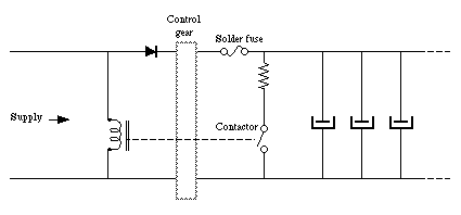
The circuit then becomes extremely simple (and less error-prone),
needing only a contactor, a diode, a solder fuse and a resistor.
http://www.poppyrecords.co.uk/other/Discharger.gif
(It is often a good idea to include a diode anyway; it will prevent
damage when the supply connections are reversed, as they almost
certainly will be, despite every precaution.)
On 08/09/2026 08:45, Liz Tuddenham wrote:
john larkin <jl@glen--canyon.com> wrote:
On Mon, 7 Sep 2026 22:26:09 +0100, liz@poppyrecords.invalid.invalid
(Liz Tuddenham) wrote:
john larkin <jl@glen--canyon.com> wrote:Maybe. But any failure mode could start a fire.
On Mon, 7 Sep 2026 21:18:48 +0200, Lasse Langwadt <llc@fonz.dk> wrote: >>>>
On 9/7/26 17:18, john larkin wrote:
Suppose we have a box with some big caps inside, for example 0.2 >>>>>> farads that run at about 200 volts. When AC power is off, we want to >>>>>> discharge them for several reasons.
Putting, say, a 1K resistor across them dissipates 40 watts and has a >>>>>> 200 second time constant. It will take many tau before the voltage >>>>>> gets low enough for people to poke around inside.
The ideal discharger would be a constant-current or even better a >>>>>> constant-power load, all the way down to zero volts. It would be dumb, >>>>>> not switched by some decision circuit or anything fancy like that. >>>>>>
And of course we need several LEDs as warnings that the thing is hot. >>>>>>
is a relay (or two) controlled by the AC not dumb enough?
maybe use a PTC self limiting heater to dump the energy in
We get DC power, and I wouldn't like the relay to fail anyhow and
start a fire.
The load-dump resistor of a fairly large CNC milling machine was
controlled by a power FET; twice in two years the FET failed and the
resistor, which was in a cage on the top of the control cabinet, ran red >>> hot. A temperature sensor inside the cabinet eventually shut the
machine down.
A PTC might work. It would sit there and get hot all the time and go >>>> sorta constant-power as the caps discharge. Maybe some PTCs and some >>>> series resistors, to not spike to a zillion amps at startup.
The DC power supply might not start up if it had a true constant-power >>>> load.
Could you have a current-operated relay in the incoming supply with
normally-closed contacts that bring in a contactor for the discharge
current? The contactor could be supplied by the power it is discharging >>> and would automatically drop out when the voltsge reached a safe level. >>
Connect the incoming supply with a short length of solder wire close to
the resistor.
Steady-state, the cap charging current can be zero.
If the circuit is fed with DC, without access to the incoming AC supply, how will you detect mains failure? If you have half a volt to spare
and you put a diode in the supply line, then you could use a voltage
relay as a detector on the supply side of the diode. You could actually power a normally-closed contactor directly off the supply.
The circuit then becomes extremely simple (and less error-prone),
needing only a contactor, a diode, a solder fuse and a resistor.
http://www.poppyrecords.co.uk/other/Discharger.gif
(It is often a good idea to include a diode anyway; it will prevent damage when the supply connections are reversed, as they almost
certainly will be, despite every precaution.)
I'm not sure that a length of solder wire would make a very
safe fuse. You might end up with a spectacular arc.
On 9/7/26 19:52, john larkin wrote:
On Mon, 7 Sep 2026 19:33:35 +0100, chrisq <syseng@gfsys.co.uk> wrote:
On 9/7/26 16:18, john larkin wrote:
Suppose we have a box with some big caps inside, for example 0.2
farads that run at about 200 volts. When AC power is off, we want to
discharge them for several reasons.
Putting, say, a 1K resistor across them dissipates 40 watts and has a
200 second time constant. It will take many tau before the voltage
gets low enough for people to poke around inside.
The ideal discharger would be a constant-current or even better a
constant-power load, all the way down to zero volts. It would be dumb, >>>> not switched by some decision circuit or anything fancy like that.
And of course we need several LEDs as warnings that the thing is hot.
What sort of design needs 0.2 Farad cap, at 200 volts ?. If you are
working at that level, put in a cheap relay and a rated heatsink
wirewound resistor to dump the energy, when the power goes off.
Cheap, and lossless as well. Motor drive inverters often have
big resistors to brake the motor.
John Larkin
Highland Tech Glen Canyon Design Center
Lunatic Fringe Electronics
It's a 1500 amp laser driver.
The input to our box is DC, from an external power supply.
I do want a circuit that's foolproof, that always discharges the caps
but doen't often go up in flames.
A resistor makes an exponential decay which could be a very long time
to get down to safe levels.
No doubt you could calculate the correct resistor value, discharge
time, and other parameters, but need to specify what is the target >performance, which hasn't been specified.
I thought the group might like a circuit design problem once in a
while, a break from politics.
Great idea, but the a relay and resistor combo is about as simple as
it gets, and if you are really paranoid, use two relays.
You could also use a thyristor, but then you have the complication and >possible reliability issues of a triggering circuit.
John Larkin
Highland Tech Glen Canyon Design Center
Lunatic Fringe Electronics
chrisq <syseng@gfsys.co.uk>wrote:
On 9/7/26 16:18, john larkin wrote:
Suppose we have a box with some big caps inside, for example 0.2
farads that run at about 200 volts. When AC power is off, we want to
discharge them for several reasons.
Putting, say, a 1K resistor across them dissipates 40 watts and has a
200 second time constant. It will take many tau before the voltage
gets low enough for people to poke around inside.
The ideal discharger would be a constant-current or even better a
constant-power load, all the way down to zero volts. It would be dumb,
not switched by some decision circuit or anything fancy like that.
And of course we need several LEDs as warnings that the thing is hot.
What sort of design needs 0.2 Farad cap, at 200 volts ?. If you are
working at that level, put in a cheap relay and a rated heatsink
wirewound resistor to dump the energy, when the power goes off.
Cheap, and lossless as well. Motor drive inverters often have
big resistors to brake the motor.
No relay, use an thyristor
On Mon, 7 Sep 2026 17:20:07 +0100, Simon Simple
<nothanks@nottoday.co.uk> wrote:
On 07/09/2026 16:18, john larkin wrote:
Suppose we have a box with some big caps inside, for example 0.2
farads that run at about 200 volts. When AC power is off, we want to
discharge them for several reasons.
Putting, say, a 1K resistor across them dissipates 40 watts and has a
200 second time constant. It will take many tau before the voltage
gets low enough for people to poke around inside.
The ideal discharger would be a constant-current or even better a
constant-power load, all the way down to zero volts. It would be dumb,
not switched by some decision circuit or anything fancy like that.
And of course we need several LEDs as warnings that the thing is hot.
John Larkin
Highland Tech Glen Canyon Design Center
Lunatic Fringe Electronics
Well 200V and 200mF is 4kJ.
Have you ever shorted a kilojoule joule of capacitors with a
screwdriver? It's an impressive explosion.
It's looking like we might actually have 0.12F at 150v, which is
merely 1300J.
So not too much heat from, say, a kettle or hotplate element. Or an
array of 20 incandescent lamps to add a nice warning display. >>Incandescents are a bit constant-powery too.
O O OOO OOO
OOO O O O
O O OOO O
Keeps it simple.
Incandescent is interesting. Running red hot, they would last forever.
One would have to consider startup, when they are cold. Don't want to
hang up the power supply. So I guess we prefer constant-currrent, not
so much constant-power.
AI says that an incandescent cold resistance might be 1/10 of hot.
That might be OK.
John Larkin
Highland Tech Glen Canyon Design Center
Lunatic Fringe Electronics
john larkin <jl@glen--canyon.com> wrote:
On Mon, 7 Sep 2026 22:26:09 +0100, liz@poppyrecords.invalid.invalid
(Liz Tuddenham) wrote:
john larkin <jl@glen--canyon.com> wrote:
On Mon, 7 Sep 2026 21:18:48 +0200, Lasse Langwadt <llc@fonz.dk> wrote:
On 9/7/26 17:18, john larkin wrote:
Suppose we have a box with some big caps inside, for example 0.2
farads that run at about 200 volts. When AC power is off, we want to >> >> >> discharge them for several reasons.
Putting, say, a 1K resistor across them dissipates 40 watts and has a >> >> >> 200 second time constant. It will take many tau before the voltage
gets low enough for people to poke around inside.
The ideal discharger would be a constant-current or even better a
constant-power load, all the way down to zero volts. It would be dumb, >> >> >> not switched by some decision circuit or anything fancy like that.
And of course we need several LEDs as warnings that the thing is hot. >> >> >>
is a relay (or two) controlled by the AC not dumb enough?
maybe use a PTC self limiting heater to dump the energy in
We get DC power, and I wouldn't like the relay to fail anyhow and
start a fire.
The load-dump resistor of a fairly large CNC milling machine was
controlled by a power FET; twice in two years the FET failed and the
resistor, which was in a cage on the top of the control cabinet, ran red
hot. A temperature sensor inside the cabinet eventually shut the
machine down.
A PTC might work. It would sit there and get hot all the time and go
sorta constant-power as the caps discharge. Maybe some PTCs and some
series resistors, to not spike to a zillion amps at startup.
The DC power supply might not start up if it had a true constant-power
load.
Could you have a current-operated relay in the incoming supply with
normally-closed contacts that bring in a contactor for the discharge
current? The contactor could be supplied by the power it is discharging
and would automatically drop out when the voltsge reached a safe level.
Maybe. But any failure mode could start a fire.
Connect the incoming supply with a short length of solder wire close to
the resistor.
Steady-state, the cap charging current can be zero.
If the circuit is fed with DC, without access to the incoming AC supply,
how will you detect mains failure? If you have half a volt to spare
and you put a diode in the supply line, then you could use a voltage
relay as a detector on the supply side of the diode. You could actually >power a normally-closed contactor directly off the supply.
The circuit then becomes extremely simple (and less error-prone),
needing only a contactor, a diode, a solder fuse and a resistor.
http://www.poppyrecords.co.uk/other/Discharger.gif
(It is often a good idea to include a diode anyway; it will prevent
damage when the supply connections are reversed, as they almost
certainly will be, despite every precaution.)
Suppose we have a box with some big caps inside, for example 0.2
farads that run at about 200 volts. When AC power is off, we want to >discharge them for several reasons.
Putting, say, a 1K resistor across them dissipates 40 watts and has a
200 second time constant. It will take many tau before the voltage
gets low enough for people to poke around inside.
The ideal discharger would be a constant-current or even better a >constant-power load, all the way down to zero volts. It would be dumb,
not switched by some decision circuit or anything fancy like that.
And of course we need several LEDs as warnings that the thing is hot.
John Larkin
Highland Tech Glen Canyon Design Center
Lunatic Fringe Electronics
On 8/09/2026 4:52 am, john larkin wrote:
On Mon, 7 Sep 2026 19:33:35 +0100, chrisq <syseng@gfsys.co.uk> wrote:
On 9/7/26 16:18, john larkin wrote:
Suppose we have a box with some big caps inside, for example 0.2
farads that run at about 200 volts. When AC power is off, we want to
discharge them for several reasons.
Putting, say, a 1K resistor across them dissipates 40 watts and has a
200 second time constant. It will take many tau before the voltage
gets low enough for people to poke around inside.
The ideal discharger would be a constant-current or even better a
constant-power load, all the way down to zero volts. It would be dumb, >>>> not switched by some decision circuit or anything fancy like that.
And of course we need several LEDs as warnings that the thing is hot.
What sort of design needs 0.2 Farad cap, at 200 volts ?. If you are
working at that level, put in a cheap relay and a rated heatsink
wirewound resistor to dump the energy, when the power goes off.
Cheap, and lossless as well. Motor drive inverters often have
big resistors to brake the motor.
John Larkin
Highland Tech Glen Canyon Design Center
Lunatic Fringe Electronics
It's a 1500 amp laser driver.
The input to our box is DC, from an external power supply.
I do want a circuit that's foolproof, that always discharges the caps
but doen't often go up in flames.
A resistor makes an exponential decay which could be a very long time
to get down to safe levels.
But a resistor plus an inductor could give a critically damped decay,
which would be quite a bit faster. I don't know enough about the circuit
to be prepared to try to work out how much inductance you'd need, and
you clearly can't be bothered.
I thought the group might like a circuit design problem once in a
while, a break from politics.
But you don't do circuit design, and this sort of question makes it
obvious why you don't.
john larkin <jl@glen--canyon.com>wrote:
On Mon, 7 Sep 2026 12:26:10 -0400, ehsjr <ehsjr@verizon.net> wrote:
On 9/7/2026 11:18 AM, john larkin wrote:
Suppose we have a box with some big caps inside, for example 0.2
farads that run at about 200 volts. When AC power is off, we want to
discharge them for several reasons.
Putting, say, a 1K resistor across them dissipates 40 watts and has a
200 second time constant. It will take many tau before the voltage
gets low enough for people to poke around inside.
The ideal discharger would be a constant-current or even better a
constant-power load, all the way down to zero volts. It would be dumb, >>>> not switched by some decision circuit or anything fancy like that.
And of course we need several LEDs as warnings that the thing is hot.
John Larkin
Highland Tech Glen Canyon Design Center
Lunatic Fringe Electronics
Motor generator?
Ed
Maybe not available in surface mount. And the heat still needs to go >>somewhere.
Electric chair, sell it to trump?
On 8/09/2026 4:52 am, john larkin wrote:
On Mon, 7 Sep 2026 19:33:35 +0100, chrisq <syseng@gfsys.co.uk> wrote:
On 9/7/26 16:18, john larkin wrote:
Suppose we have a box with some big caps inside, for example 0.2
farads that run at about 200 volts. When AC power is off, we want to
discharge them for several reasons.
Putting, say, a 1K resistor across them dissipates 40 watts and has a
200 second time constant. It will take many tau before the voltage
gets low enough for people to poke around inside.
The ideal discharger would be a constant-current or even better a
constant-power load, all the way down to zero volts. It would be dumb, >>>> not switched by some decision circuit or anything fancy like that.
And of course we need several LEDs as warnings that the thing is hot.
What sort of design needs 0.2 Farad cap, at 200 volts ?. If you are
working at that level, put in a cheap relay and a rated heatsink
wirewound resistor to dump the energy, when the power goes off.
Cheap, and lossless as well. Motor drive inverters often have
big resistors to brake the motor.
John Larkin
Highland Tech Glen Canyon Design Center
Lunatic Fringe Electronics
It's a 1500 amp laser driver.
The input to our box is DC, from an external power supply.
I do want a circuit that's foolproof, that always discharges the caps
but doen't often go up in flames.
A resistor makes an exponential decay which could be a very long time
to get down to safe levels.
But a resistor plus an inductor could give a critically damped decay,
which would be quite a bit faster. I don't know enough about the circuit
to be prepared to try to work out how much inductance you'd need, and
you clearly can't be bothered.
I thought the group might like a circuit design problem once in a
while, a break from politics.
But you don't do circuit design, and this sort of question makes it
obvious why you don't.
On Mon, 07 Sep 2026 09:58:51 -0700, john larkin <jl@glen--canyon.com>
wrote:
On Mon, 7 Sep 2026 17:20:07 +0100, Simon Simple
<nothanks@nottoday.co.uk> wrote:
On 07/09/2026 16:18, john larkin wrote:
Suppose we have a box with some big caps inside, for example 0.2
farads that run at about 200 volts. When AC power is off, we want to
discharge them for several reasons.
Besides safety, would you care to name them?
Or is this 'problematic', as in I'm too lazy to get into it, or the
decision isn't mine to make.
Putting, say, a 1K resistor across them dissipates 40 watts and has a
200 second time constant. It will take many tau before the voltage
gets low enough for people to poke around inside.
One of your basic problem specifications IS the time element, if
discharge is mandated.
The ideal discharger would be a constant-current or even better a
constant-power load, all the way down to zero volts. It would be dumb, >>>> not switched by some decision circuit or anything fancy like that.
And of course we need several LEDs as warnings that the thing is hot.
There are regs covering warning indications of all types. Hot
surfaces, voltage, energy, pinch points, radiation etc. Refer to
them. They vary for user accessible or maintenace-only accessible
locations.
Just because you think you're doing it right, doesn't mean that you
are. Good intentions sometimes are just not enough.
John Larkin
Highland Tech Glen Canyon Design Center
Lunatic Fringe Electronics
Well 200V and 200mF is 4kJ.
Have you ever shorted a kilojoule joule of capacitors with a
screwdriver? It's an impressive explosion.
I think we can all safely assume that this one of the things you're >attempting to avoid. Or is this a funny joke?
It's looking like we might actually have 0.12F at 150v, which is
merely 1300J.
So not too much heat from, say, a kettle or hotplate element. Or an >>>array of 20 incandescent lamps to add a nice warning display. >>>Incandescents are a bit constant-powery too.
O O OOO OOO
OOO O O O
O O OOO O
Keeps it simple.
As long as 240V (European?) incandescent lamps remain commodity.
Incandescent (PTC) elements won't work in series, so no 120V
hardware doubled up.
Incandescent is interesting. Running red hot, they would last forever.
Aaaahh . . it's the red hot business that shortens their life. Or were
you making another funny joke?
One would have to consider startup, when they are cold. Don't want to
hang up the power supply. So I guess we prefer constant-currrent, not
so much constant-power.
We prefer that you think about it, before posting.
AI says that an incandescent cold resistance might be 1/10 of hot.
That might be OK.
John Larkin
Highland Tech Glen Canyon Design Center
Lunatic Fringe Electronics
john larkin <jl@glen--canyon.com>wrote:
On Tue, 08 Sep 2026 07:41:09 GMT, Jan Panteltje <alien@comet.invalid>wrote:
john larkin <jl@glen--canyon.com>wrote:
On Mon, 7 Sep 2026 12:26:10 -0400, ehsjr <ehsjr@verizon.net> wrote:
On 9/7/2026 11:18 AM, john larkin wrote:
Suppose we have a box with some big caps inside, for example 0.2
farads that run at about 200 volts. When AC power is off, we want to >>>>> discharge them for several reasons.
Putting, say, a 1K resistor across them dissipates 40 watts and has a >>>>> 200 second time constant. It will take many tau before the voltage
gets low enough for people to poke around inside.
The ideal discharger would be a constant-current or even better a
constant-power load, all the way down to zero volts. It would be dumb, >>>>> not switched by some decision circuit or anything fancy like that.
And of course we need several LEDs as warnings that the thing is hot. >>>>>
John Larkin
Highland Tech Glen Canyon Design Center
Lunatic Fringe Electronics
Motor generator?
Ed
Maybe not available in surface mount. And the heat still needs to go >>>somewhere.
Electric chair, sell it to trump?
Test it carefully first.
It didn't take long for an idiot to mention DT in a circuit design
thread. Whatever turns you on.
On Tue, 8 Sep 2026 11:19:33 +0100, chrisq <syseng@gfsys.co.uk> wrote:
On 9/7/26 19:52, john larkin wrote:
On Mon, 7 Sep 2026 19:33:35 +0100, chrisq <syseng@gfsys.co.uk> wrote:
On 9/7/26 16:18, john larkin wrote:
Suppose we have a box with some big caps inside, for example 0.2
farads that run at about 200 volts. When AC power is off, we want to >>>>> discharge them for several reasons.
Putting, say, a 1K resistor across them dissipates 40 watts and has a >>>>> 200 second time constant. It will take many tau before the voltage
gets low enough for people to poke around inside.
The ideal discharger would be a constant-current or even better a
constant-power load, all the way down to zero volts. It would be dumb, >>>>> not switched by some decision circuit or anything fancy like that.
And of course we need several LEDs as warnings that the thing is hot. >>>>>
What sort of design needs 0.2 Farad cap, at 200 volts ?. If you are
working at that level, put in a cheap relay and a rated heatsink
wirewound resistor to dump the energy, when the power goes off.
Cheap, and lossless as well. Motor drive inverters often have
big resistors to brake the motor.
John Larkin
Highland Tech Glen Canyon Design Center
Lunatic Fringe Electronics
It's a 1500 amp laser driver.
The input to our box is DC, from an external power supply.
I do want a circuit that's foolproof, that always discharges the caps
but doen't often go up in flames.
A resistor makes an exponential decay which could be a very long time
to get down to safe levels.
No doubt you could calculate the correct resistor value, discharge
time, and other parameters, but need to specify what is the target
performance, which hasn't been specified.
I said what I want to do in my original post: discharge 0.2F charged
to 200v, in a couple of minutes. Later posts clarified that I want it
to be safe and foolproof and discharge all the way.
I thought the group might like a circuit design problem once in a
while, a break from politics.
Great idea, but the a relay and resistor combo is about as simple as
it gets, and if you are really paranoid, use two relays.
I can't think of a simple, safe way to drive the relay coils.
And how do you think the relay contacts should be wired? Would a coil
failure discharge the caps, or would it not?
You could also use a thyristor, but then you have the complication and
possible reliability issues of a triggering circuit.
And a thyristor would stay on once it was triggered.
John Larkin
Highland Tech Glen Canyon Design Center
Lunatic Fringe Electronics
John Larkin
Highland Tech Glen Canyon Design Center
Lunatic Fringe Electronics
On Mon, 07 Sep 2026 09:58:51 -0700, john larkin <jl@glen--canyon.com>
wrote:
On Mon, 7 Sep 2026 17:20:07 +0100, Simon Simple
<nothanks@nottoday.co.uk> wrote:
On 07/09/2026 16:18, john larkin wrote:
Suppose we have a box with some big caps inside, for example 0.2
farads that run at about 200 volts. When AC power is off, we want to
discharge them for several reasons.
Besides safety, would you care to name them?
Or is this 'problematic', as in I'm too lazy to get into it, or the
decision isn't mine to make.
Putting, say, a 1K resistor across them dissipates 40 watts and has a
200 second time constant. It will take many tau before the voltage
gets low enough for people to poke around inside.
One of your basic problem specifications IS the time element, if
discharge is mandated.
The ideal discharger would be a constant-current or even better a
constant-power load, all the way down to zero volts. It would be dumb, >>>> not switched by some decision circuit or anything fancy like that.
And of course we need several LEDs as warnings that the thing is hot.
There are regs covering warning indications of all types. Hot
surfaces, voltage, energy, pinch points, radiation etc. Refer to
them. They vary for user accessible or maintenace-only accessible
locations.
Just because you think you're doing it right, doesn't mean that you
are. Good intentions sometimes are just not enough.
John Larkin
Highland Tech Glen Canyon Design Center
Lunatic Fringe Electronics
Well 200V and 200mF is 4kJ.
Have you ever shorted a kilojoule joule of capacitors with a
screwdriver? It's an impressive explosion.
I think we can all safely assume that this one of the things you're attempting to avoid. Or is this a funny joke?
It's looking like we might actually have 0.12F at 150v, which is
merely 1300J.
So not too much heat from, say, a kettle or hotplate element. Or an
array of 20 incandescent lamps to add a nice warning display.
Incandescents are a bit constant-powery too.
O O OOO OOO
OOO O O O
O O OOO O
Keeps it simple.
As long as 240V (European?) incandescent lamps remain commodity.
Incandescent (PTC) elements won't work in series, so no 120V
hardware doubled up.
Incandescent is interesting. Running red hot, they would last forever.
Aaaahh . . it's the red hot business that shortens their life. Or were
you making another funny joke?
On Tue, 8 Sep 2026 17:35:24 +1000, Bill Sloman <bill.sloman@ieee.org>
wrote:
On 8/09/2026 4:52 am, john larkin wrote:
On Mon, 7 Sep 2026 19:33:35 +0100, chrisq <syseng@gfsys.co.uk> wrote:
On 9/7/26 16:18, john larkin wrote:
Suppose we have a box with some big caps inside, for example 0.2
farads that run at about 200 volts. When AC power is off, we want to >>>>> discharge them for several reasons.
Putting, say, a 1K resistor across them dissipates 40 watts and has a >>>>> 200 second time constant. It will take many tau before the voltage
gets low enough for people to poke around inside.
The ideal discharger would be a constant-current or even better a
constant-power load, all the way down to zero volts. It would be dumb, >>>>> not switched by some decision circuit or anything fancy like that.
And of course we need several LEDs as warnings that the thing is hot. >>>>>
What sort of design needs 0.2 Farad cap, at 200 volts ?. If you are
working at that level, put in a cheap relay and a rated heatsink
wirewound resistor to dump the energy, when the power goes off.
Cheap, and lossless as well. Motor drive inverters often have
big resistors to brake the motor.
John Larkin
Highland Tech Glen Canyon Design Center
Lunatic Fringe Electronics
It's a 1500 amp laser driver.
The input to our box is DC, from an external power supply.
I do want a circuit that's foolproof, that always discharges the caps
but doen't often go up in flames.
A resistor makes an exponential decay which could be a very long time
to get down to safe levels.
But a resistor plus an inductor could give a critically damped decay,
which would be quite a bit faster. I don't know enough about the circuit
to be prepared to try to work out how much inductance you'd need, and
you clearly can't be bothered.
I thought the group might like a circuit design problem once in a
while, a break from politics.
But you don't do circuit design, and this sort of question makes it
obvious why you don't.
Of course I'm a circuit designer. I've posted tons of circuits here.
Maybe my favorite is my instant-start LC oscillator. The latest one,
50 MHz, has period jitter of a couple PPM and an uncompensated tempco
of 3 PPM/K.
Another recent one, the 50 cent DDS, ain't bad.
On Tue, 8 Sep 2026 11:19:33 +0100, chrisq <syseng@gfsys.co.uk> wrote:
On 9/7/26 19:52, john larkin wrote:
On Mon, 7 Sep 2026 19:33:35 +0100, chrisq <syseng@gfsys.co.uk> wrote:
On 9/7/26 16:18, john larkin wrote:
Suppose we have a box with some big caps inside, for example 0.2
farads that run at about 200 volts. When AC power is off, we want to >>>>> discharge them for several reasons.
Putting, say, a 1K resistor across them dissipates 40 watts and has a >>>>> 200 second time constant. It will take many tau before the voltage
gets low enough for people to poke around inside.
The ideal discharger would be a constant-current or even better a
constant-power load, all the way down to zero volts. It would be dumb, >>>>> not switched by some decision circuit or anything fancy like that.
And of course we need several LEDs as warnings that the thing is hot. >>>>>
What sort of design needs 0.2 Farad cap, at 200 volts ?. If you are
working at that level, put in a cheap relay and a rated heatsink
wirewound resistor to dump the energy, when the power goes off.
Cheap, and lossless as well. Motor drive inverters often have
big resistors to brake the motor.
John Larkin
Highland Tech Glen Canyon Design Center
Lunatic Fringe Electronics
It's a 1500 amp laser driver.
The input to our box is DC, from an external power supply.
I do want a circuit that's foolproof, that always discharges the caps
but doen't often go up in flames.
A resistor makes an exponential decay which could be a very long time
to get down to safe levels.
No doubt you could calculate the correct resistor value, discharge
time, and other parameters, but need to specify what is the target
performance, which hasn't been specified.
I said what I want to do in my original post: discharge 0.2F charged
to 200v, in a couple of minutes. Later posts clarified that I want it
to be safe and foolproof and discharge all the way.
I thought the group might like a circuit design problem once in a
while, a break from politics.
Great idea, but the a relay and resistor combo is about as simple as
it gets, and if you are really paranoid, use two relays.
I can't think of a simple, safe way to drive the relay coils.
And how do you think the relay contacts should be wired? Would a coil
failure discharge the caps, or would it not?
You could also use a thyristor, but then you have the complication and
possible reliability issues of a triggering circuit.
And a thyristor would stay on once it was triggered.
On Tue, 8 Sep 2026 11:19:33 +0100, chrisq <syseng@gfsys.co.uk> wrote:
On 9/7/26 19:52, john larkin wrote:
On Mon, 7 Sep 2026 19:33:35 +0100, chrisq <syseng@gfsys.co.uk> wrote:
On 9/7/26 16:18, john larkin wrote:
Suppose we have a box with some big caps inside, for example 0.2
farads that run at about 200 volts. When AC power is off, we want to >>>>> discharge them for several reasons.
Putting, say, a 1K resistor across them dissipates 40 watts and has a >>>>> 200 second time constant. It will take many tau before the voltage
gets low enough for people to poke around inside.
The ideal discharger would be a constant-current or even better a
constant-power load, all the way down to zero volts. It would be dumb, >>>>> not switched by some decision circuit or anything fancy like that.
And of course we need several LEDs as warnings that the thing is hot. >>>>>
What sort of design needs 0.2 Farad cap, at 200 volts ?. If you are
working at that level, put in a cheap relay and a rated heatsink
wirewound resistor to dump the energy, when the power goes off.
Cheap, and lossless as well. Motor drive inverters often have
big resistors to brake the motor.
John Larkin
Highland Tech Glen Canyon Design Center
Lunatic Fringe Electronics
It's a 1500 amp laser driver.
The input to our box is DC, from an external power supply.
I do want a circuit that's foolproof, that always discharges the caps
but doen't often go up in flames.
A resistor makes an exponential decay which could be a very long time
to get down to safe levels.
No doubt you could calculate the correct resistor value, discharge
time, and other parameters, but need to specify what is the target
performance, which hasn't been specified.
I said what I want to do in my original post: discharge 0.2F charged
to 200v, in a couple of minutes. Later posts clarified that I want it
to be safe and foolproof and discharge all the way.
I thought the group might like a circuit design problem once in a
while, a break from politics.
Great idea, but the a relay and resistor combo is about as simple as
it gets, and if you are really paranoid, use two relays.
I can't think of a simple, safe way to drive the relay coils.
And how do you think the relay contacts should be wired? Would a coil
failure discharge the caps, or would it not?
You could also use a thyristor, but then you have the complication and
possible reliability issues of a triggering circuit.
And a thyristor would stay on once it was triggered.
legg <legg@nospam.magma.ca> wrote:
On Mon, 07 Sep 2026 09:58:51 -0700, john larkin <jl@glen--canyon.com>
wrote:
On Mon, 7 Sep 2026 17:20:07 +0100, Simon Simple
<nothanks@nottoday.co.uk> wrote:
On 07/09/2026 16:18, john larkin wrote:
Suppose we have a box with some big caps inside, for example 0.2
farads that run at about 200 volts. When AC power is off, we want to >>>>> discharge them for several reasons.
Besides safety, would you care to name them?
Or is this 'problematic', as in I'm too lazy to get into it, or the
decision isn't mine to make.
Putting, say, a 1K resistor across them dissipates 40 watts and has a >>>>> 200 second time constant. It will take many tau before the voltage
gets low enough for people to poke around inside.
One of your basic problem specifications IS the time element, if
discharge is mandated.
The ideal discharger would be a constant-current or even better a
constant-power load, all the way down to zero volts. It would be dumb, >>>>> not switched by some decision circuit or anything fancy like that.
And of course we need several LEDs as warnings that the thing is hot.
There are regs covering warning indications of all types. Hot
surfaces, voltage, energy, pinch points, radiation etc. Refer to
them. They vary for user accessible or maintenace-only accessible
locations.
Just because you think you're doing it right, doesn't mean that you
are. Good intentions sometimes are just not enough.
John Larkin
Highland Tech Glen Canyon Design Center
Lunatic Fringe Electronics
Well 200V and 200mF is 4kJ.
Have you ever shorted a kilojoule joule of capacitors with a
screwdriver? It's an impressive explosion.
I think we can all safely assume that this one of the things you're
attempting to avoid. Or is this a funny joke?
It's looking like we might actually have 0.12F at 150v, which is
merely 1300J.
So not too much heat from, say, a kettle or hotplate element. Or an
array of 20 incandescent lamps to add a nice warning display.
Incandescents are a bit constant-powery too.
O O OOO OOO
OOO O O O
O O OOO O
Keeps it simple.
As long as 240V (European?) incandescent lamps remain commodity.
Incandescent (PTC) elements won't work in series, so no 120V
hardware doubled up.
Incandescent is interesting. Running red hot, they would last forever.
Aaaahh . . it's the red hot business that shortens their life. Or were
you making another funny joke?
John?s quite right about the bulb. Filament life goes as some absurdly high >negative power of temperature, so dropping it by a factor of two could
easily extend its life by thousands of times.
One drawback is that European bulbs are more fragile due to their thinner >filaments.
One could think of using a top side depletion NFET with a voltage divider
on the gate, plus a smaller-value power resistor from S to ground. And >probably a fuse in series in case the FET shorts.
Cheers
Phil Hobbs
john larkin <jl@glen--canyon.com>wrote:
On Tue, 08 Sep 2026 07:41:09 GMT, Jan Panteltje <alien@comet.invalid> >>wrote:
john larkin <jl@glen--canyon.com>wrote:
On Mon, 7 Sep 2026 12:26:10 -0400, ehsjr <ehsjr@verizon.net> wrote:
On 9/7/2026 11:18 AM, john larkin wrote:
Suppose we have a box with some big caps inside, for example 0.2
farads that run at about 200 volts. When AC power is off, we want to >>>>>> discharge them for several reasons.
Putting, say, a 1K resistor across them dissipates 40 watts and has a >>>>>> 200 second time constant. It will take many tau before the voltage >>>>>> gets low enough for people to poke around inside.
The ideal discharger would be a constant-current or even better a
constant-power load, all the way down to zero volts. It would be dumb, >>>>>> not switched by some decision circuit or anything fancy like that. >>>>>>
And of course we need several LEDs as warnings that the thing is hot. >>>>>>
John Larkin
Highland Tech Glen Canyon Design Center
Lunatic Fringe Electronics
Motor generator?
Ed
Maybe not available in surface mount. And the heat still needs to go >>>>somewhere.
Electric chair, sell it to trump?
Test it carefully first.
It didn't take long for an idiot to mention DT in a circuit design
thread. Whatever turns you on.
You wanted a load !
Criminals have been a legal load as punishment in the YouASh for years.
A bit touchy, aren't you?
Fussion fan
Bye the waaay
You can use 2 thyristors, one to switch that chair on,
and the other one in series with the power input functioning as diode
that only is allowed to go on when the discharge of your chair is complete, >easy one for a smart designer like you, just a few components.
On Tue, 8 Sep 2026 08:45:44 +0100, liz@poppyrecords.invalid.invalid
(Liz Tuddenham) wrote:
john larkin <jl@glen--canyon.com> wrote:
On Mon, 7 Sep 2026 22:26:09 +0100, liz@poppyrecords.invalid.invalid
(Liz Tuddenham) wrote:
john larkin <jl@glen--canyon.com> wrote:Maybe. But any failure mode could start a fire.
On Mon, 7 Sep 2026 21:18:48 +0200, Lasse Langwadt <llc@fonz.dk> wrote: >>>>>
On 9/7/26 17:18, john larkin wrote:
Suppose we have a box with some big caps inside, for example 0.2 >>>>>>> farads that run at about 200 volts. When AC power is off, we want to >>>>>>> discharge them for several reasons.
Putting, say, a 1K resistor across them dissipates 40 watts and has a >>>>>>> 200 second time constant. It will take many tau before the voltage >>>>>>> gets low enough for people to poke around inside.
The ideal discharger would be a constant-current or even better a >>>>>>> constant-power load, all the way down to zero volts. It would be dumb, >>>>>>> not switched by some decision circuit or anything fancy like that. >>>>>>>
And of course we need several LEDs as warnings that the thing is hot. >>>>>>>
is a relay (or two) controlled by the AC not dumb enough?
maybe use a PTC self limiting heater to dump the energy in
We get DC power, and I wouldn't like the relay to fail anyhow and
start a fire.
The load-dump resistor of a fairly large CNC milling machine was
controlled by a power FET; twice in two years the FET failed and the
resistor, which was in a cage on the top of the control cabinet, ran red >>>> hot. A temperature sensor inside the cabinet eventually shut the
machine down.
A PTC might work. It would sit there and get hot all the time and go >>>>> sorta constant-power as the caps discharge. Maybe some PTCs and some >>>>> series resistors, to not spike to a zillion amps at startup.
The DC power supply might not start up if it had a true constant-power >>>>> load.
Could you have a current-operated relay in the incoming supply with
normally-closed contacts that bring in a contactor for the discharge
current? The contactor could be supplied by the power it is discharging >>>> and would automatically drop out when the voltsge reached a safe level. >>>
Connect the incoming supply with a short length of solder wire close to
the resistor.
Or buy a real fuse.
Steady-state, the cap charging current can be zero.
If the circuit is fed with DC, without access to the incoming AC supply,
how will you detect mains failure? If you have half a volt to spare
and you put a diode in the supply line, then you could use a voltage
relay as a detector on the supply side of the diode. You could actually
power a normally-closed contactor directly off the supply.
The circuit then becomes extremely simple (and less error-prone),
needing only a contactor, a diode, a solder fuse and a resistor.
http://www.poppyrecords.co.uk/other/Discharger.gif
Something like that would work. I'd need a big diode with a heat sink,
but that's not a show stopper. The power supply is
programmable/variable, so the contactor would have to work over the
voltage range. That's managable too.
(It is often a good idea to include a diode anyway; it will prevent
damage when the supply connections are reversed, as they almost
certainly will be, despite every precaution.)
Yikes. Let's hope not. The power feed is connectorized.
John Larkin
Highland Tech Glen Canyon Design Center
Lunatic Fringe Electronics
On Tue, 8 Sep 2026 17:35:24 +1000, Bill Sloman <bill.sloman@ieee.org>
wrote:
On 8/09/2026 4:52 am, john larkin wrote:
On Mon, 7 Sep 2026 19:33:35 +0100, chrisq <syseng@gfsys.co.uk> wrote:
On 9/7/26 16:18, john larkin wrote:
Suppose we have a box with some big caps inside, for example 0.2
farads that run at about 200 volts. When AC power is off, we want to >>>>> discharge them for several reasons.
Putting, say, a 1K resistor across them dissipates 40 watts and has a >>>>> 200 second time constant. It will take many tau before the voltage
gets low enough for people to poke around inside.
The ideal discharger would be a constant-current or even better a
constant-power load, all the way down to zero volts. It would be dumb, >>>>> not switched by some decision circuit or anything fancy like that.
And of course we need several LEDs as warnings that the thing is hot. >>>>>
What sort of design needs 0.2 Farad cap, at 200 volts ?. If you are
working at that level, put in a cheap relay and a rated heatsink
wirewound resistor to dump the energy, when the power goes off.
Cheap, and lossless as well. Motor drive inverters often have
big resistors to brake the motor.
John Larkin
Highland Tech Glen Canyon Design Center
Lunatic Fringe Electronics
It's a 1500 amp laser driver.
The input to our box is DC, from an external power supply.
I do want a circuit that's foolproof, that always discharges the caps
but doen't often go up in flames.
A resistor makes an exponential decay which could be a very long time
to get down to safe levels.
But a resistor plus an inductor could give a critically damped decay,
which would be quite a bit faster. I don't know enough about the circuit
to be prepared to try to work out how much inductance you'd need, and
you clearly can't be bothered.
Won't be bothered.
I thought the group might like a circuit design problem once in a
while, a break from politics.
But you don't do circuit design, and this sort of question makes it
obvious why you don't.
The inductor suggestion is hilarious. Thanks.
On 9/09/2026 1:00 am, john larkin wrote:
On Tue, 8 Sep 2026 17:35:24 +1000, Bill Sloman <bill.sloman@ieee.org>
wrote:
On 8/09/2026 4:52 am, john larkin wrote:
On Mon, 7 Sep 2026 19:33:35 +0100, chrisq <syseng@gfsys.co.uk> wrote:
On 9/7/26 16:18, john larkin wrote:
Suppose we have a box with some big caps inside, for example 0.2
farads that run at about 200 volts. When AC power is off, we want to >>>>>> discharge them for several reasons.
Putting, say, a 1K resistor across them dissipates 40 watts and has a >>>>>> 200 second time constant. It will take many tau before the voltage >>>>>> gets low enough for people to poke around inside.
The ideal discharger would be a constant-current or even better a
constant-power load, all the way down to zero volts. It would be dumb, >>>>>> not switched by some decision circuit or anything fancy like that. >>>>>>
And of course we need several LEDs as warnings that the thing is hot. >>>>>>
What sort of design needs 0.2 Farad cap, at 200 volts ?. If you are
working at that level, put in a cheap relay and a rated heatsink
wirewound resistor to dump the energy, when the power goes off.
Cheap, and lossless as well. Motor drive inverters often have
big resistors to brake the motor.
John Larkin
Highland Tech Glen Canyon Design Center
Lunatic Fringe Electronics
It's a 1500 amp laser driver.
The input to our box is DC, from an external power supply.
I do want a circuit that's foolproof, that always discharges the caps
but doen't often go up in flames.
A resistor makes an exponential decay which could be a very long time
to get down to safe levels.
But a resistor plus an inductor could give a critically damped decay,
which would be quite a bit faster. I don't know enough about the circuit >>> to be prepared to try to work out how much inductance you'd need, and
you clearly can't be bothered.
Won't be bothered.
I thought the group might like a circuit design problem once in a
while, a break from politics.
But you don't do circuit design, and this sort of question makes it
obvious why you don't.
The inductor suggestion is hilarious. Thanks.
It's elementary circuit theory, which you should have been taught and I
had to read about.
If you discharge a capacitor through a resistor, the voltage decays >exponentially. If you put an inductor in series with the resistor the >voltage decay is a more complicated function of time. If you chose the >resistance and the inductance to create a critically damped circuit, the >voltage across the capacitor will eventually decay more rapidly than
you'd see with just the resistor.
Try reading about Laplace transforms. That's a pretty hilarious
suggestion to direct at you, but you are the butt of the joke.
On 9/09/2026 12:23 am, john larkin wrote:
On Tue, 8 Sep 2026 11:19:33 +0100, chrisq <syseng@gfsys.co.uk> wrote:
On 9/7/26 19:52, john larkin wrote:
On Mon, 7 Sep 2026 19:33:35 +0100, chrisq <syseng@gfsys.co.uk> wrote:
On 9/7/26 16:18, john larkin wrote:
Suppose we have a box with some big caps inside, for example 0.2
farads that run at about 200 volts. When AC power is off, we want to >>>>>> discharge them for several reasons.
Putting, say, a 1K resistor across them dissipates 40 watts and has a >>>>>> 200 second time constant. It will take many tau before the voltage >>>>>> gets low enough for people to poke around inside.
The ideal discharger would be a constant-current or even better a
constant-power load, all the way down to zero volts. It would be dumb, >>>>>> not switched by some decision circuit or anything fancy like that. >>>>>>
And of course we need several LEDs as warnings that the thing is hot. >>>>>>
What sort of design needs 0.2 Farad cap, at 200 volts ?. If you are
working at that level, put in a cheap relay and a rated heatsink
wirewound resistor to dump the energy, when the power goes off.
Cheap, and lossless as well. Motor drive inverters often have
big resistors to brake the motor.
John Larkin
Highland Tech Glen Canyon Design Center
Lunatic Fringe Electronics
It's a 1500 amp laser driver.
The input to our box is DC, from an external power supply.
I do want a circuit that's foolproof, that always discharges the caps
but doen't often go up in flames.
A resistor makes an exponential decay which could be a very long time
to get down to safe levels.
No doubt you could calculate the correct resistor value, discharge
time, and other parameters, but need to specify what is the target
performance, which hasn't been specified.
I said what I want to do in my original post: discharge 0.2F charged
to 200v, in a couple of minutes. Later posts clarified that I want it
to be safe and foolproof and discharge all the way.
There's an infinite range of fools available.
I thought the group might like a circuit design problem once in a
while, a break from politics.
Great idea, but the a relay and resistor combo is about as simple as
it gets, and if you are really paranoid, use two relays.
I can't think of a simple, safe way to drive the relay coils.
No surprise there.
And how do you think the relay contacts should be wired? Would a coil
failure discharge the caps, or would it not?
You could also use a thyristor, but then you have the complication and
possible reliability issues of a triggering circuit.
And a thyristor would stay on once it was triggered.
A thyristor only stays on a long as it is carrying it's holding current.
Capacitors may keep on leaking some current for an appreciable time, but >that is eventually going to fall below the holding current.
On 9/09/2026 12:43 am, john larkin wrote:
On Tue, 8 Sep 2026 17:35:24 +1000, Bill Sloman <bill.sloman@ieee.org>
wrote:
On 8/09/2026 4:52 am, john larkin wrote:
On Mon, 7 Sep 2026 19:33:35 +0100, chrisq <syseng@gfsys.co.uk> wrote:
On 9/7/26 16:18, john larkin wrote:
Suppose we have a box with some big caps inside, for example 0.2
farads that run at about 200 volts. When AC power is off, we want to >>>>>> discharge them for several reasons.
Putting, say, a 1K resistor across them dissipates 40 watts and has a >>>>>> 200 second time constant. It will take many tau before the voltage >>>>>> gets low enough for people to poke around inside.
The ideal discharger would be a constant-current or even better a
constant-power load, all the way down to zero volts. It would be dumb, >>>>>> not switched by some decision circuit or anything fancy like that. >>>>>>
And of course we need several LEDs as warnings that the thing is hot. >>>>>>
What sort of design needs 0.2 Farad cap, at 200 volts ?. If you are
working at that level, put in a cheap relay and a rated heatsink
wirewound resistor to dump the energy, when the power goes off.
Cheap, and lossless as well. Motor drive inverters often have
big resistors to brake the motor.
John Larkin
Highland Tech Glen Canyon Design Center
Lunatic Fringe Electronics
It's a 1500 amp laser driver.
The input to our box is DC, from an external power supply.
I do want a circuit that's foolproof, that always discharges the caps
but doen't often go up in flames.
A resistor makes an exponential decay which could be a very long time
to get down to safe levels.
But a resistor plus an inductor could give a critically damped decay,
which would be quite a bit faster. I don't know enough about the circuit >>> to be prepared to try to work out how much inductance you'd need, and
you clearly can't be bothered.
I thought the group might like a circuit design problem once in a
while, a break from politics.
But you don't do circuit design, and this sort of question makes it
obvious why you don't.
Of course I'm a circuit designer. I've posted tons of circuits here.
And you think you designed them.
Maybe my favorite is my instant-start LC oscillator. The latest one,
50 MHz, has period jitter of a couple PPM and an uncompensated tempco
of 3 PPM/K.
And if you understood circuit design you'd have solved the problem
another way. You actually copied the circuit from a Hewlett Packard >original, and - when pressed - can spell out what's wrong with it.
Another recent one, the 50 cent DDS, ain't bad.
To the fond eye of the developer. If you could design circuits you could >probably have worked out what an emitter-coupled monostable does, and
why it got invented some time before it was described in Millman and
Taub back in 1956. When presented with an LTSpice simulation of one you
fell flat on your face.
On 9/8/26 15:23, john larkin wrote:
On Tue, 8 Sep 2026 11:19:33 +0100, chrisq <syseng@gfsys.co.uk> wrote:
On 9/7/26 19:52, john larkin wrote:
On Mon, 7 Sep 2026 19:33:35 +0100, chrisq <syseng@gfsys.co.uk> wrote:
On 9/7/26 16:18, john larkin wrote:
Suppose we have a box with some big caps inside, for example 0.2
farads that run at about 200 volts. When AC power is off, we want to >>>>>> discharge them for several reasons.
Putting, say, a 1K resistor across them dissipates 40 watts and has a >>>>>> 200 second time constant. It will take many tau before the voltage >>>>>> gets low enough for people to poke around inside.
The ideal discharger would be a constant-current or even better a
constant-power load, all the way down to zero volts. It would be
dumb,
not switched by some decision circuit or anything fancy like that. >>>>>>
And of course we need several LEDs as warnings that the thing is hot. >>>>>>
What sort of design needs 0.2 Farad cap, at 200 volts ?. If you are
working at that level, put in a cheap relay and a rated heatsink
wirewound resistor to dump the energy, when the power goes off.
Cheap, and lossless as well. Motor drive inverters often have
big resistors to brake the motor.
John Larkin
Highland Tech Glen Canyon Design Center
Lunatic Fringe Electronics
It's a 1500 amp laser driver.
The input to our box is DC, from an external power supply.
I do want a circuit that's foolproof, that always discharges the caps
but doen't often go up in flames.
A resistor makes an exponential decay which could be a very long time
to get down to safe levels.
No doubt you could calculate the correct resistor value, discharge
time, and other parameters, but need to specify what is the target
performance, which hasn't been specified.
I said what I want to do in my original post: discharge 0.2F charged
to 200v, in a couple of minutes. Later posts clarified that I want it
to be safe and foolproof and discharge all the way.
I thought the group might like a circuit design problem once in a
while, a break from politics.
Great idea, but the a relay and resistor combo is about as simple as
it gets, and if you are really paranoid, use two relays.
I can't think of a simple, safe way to drive the relay coils.
And how do you think the relay contacts should be wired? Would a coil
failure discharge the caps, or would it not?
Unlikely that both relays would fail at once. Both contacts in parallel across the caps and series load resistor.
If the relay contacts are normally closed, open when energised, it would
need few parts or an aux relay contact pair each, to detect an open
circuit coil, or faulty contact pair.
110v coil relays are a standard item, probably >200 as well, so at max,a fairly low wattage resistor in series, to lose a few volts.
You could also use a thyristor, but then you have the complication and
possible reliability issues of a triggering circuit.
And a thyristor would stay on once it was triggered.
John Larkin
Highland Tech Glen Canyon Design Center
Lunatic Fringe Electronics
John Larkin
Highland Tech Glen Canyon Design Center
Lunatic Fringe Electronics
On 9/8/26 16:28, chrisq wrote:
On 9/8/26 15:23, john larkin wrote:
On Tue, 8 Sep 2026 11:19:33 +0100, chrisq <syseng@gfsys.co.uk> wrote:
On 9/7/26 19:52, john larkin wrote:
On Mon, 7 Sep 2026 19:33:35 +0100, chrisq <syseng@gfsys.co.uk> wrote: >>>>>
On 9/7/26 16:18, john larkin wrote:
Suppose we have a box with some big caps inside, for example 0.2 >>>>>>> farads that run at about 200 volts. When AC power is off, we want to >>>>>>> discharge them for several reasons.
Putting, say, a 1K resistor across them dissipates 40 watts and has a >>>>>>> 200 second time constant. It will take many tau before the voltage >>>>>>> gets low enough for people to poke around inside.
The ideal discharger would be a constant-current or even better a >>>>>>> constant-power load, all the way down to zero volts. It would be >>>>>>> dumb,
not switched by some decision circuit or anything fancy like that. >>>>>>>
And of course we need several LEDs as warnings that the thing is hot. >>>>>>>
What sort of design needs 0.2 Farad cap, at 200 volts ?. If you are >>>>>> working at that level, put in a cheap relay and a rated heatsink
wirewound resistor to dump the energy, when the power goes off.
Cheap, and lossless as well. Motor drive inverters often have
big resistors to brake the motor.
John Larkin
Highland Tech Glen Canyon Design Center
Lunatic Fringe Electronics
It's a 1500 amp laser driver.
The input to our box is DC, from an external power supply.
I do want a circuit that's foolproof, that always discharges the caps >>>>> but doen't often go up in flames.
A resistor makes an exponential decay which could be a very long time >>>>> to get down to safe levels.
No doubt you could calculate the correct resistor value, discharge
time, and other parameters, but need to specify what is the target
performance, which hasn't been specified.
I said what I want to do in my original post: discharge 0.2F charged
to 200v, in a couple of minutes. Later posts clarified that I want it
to be safe and foolproof and discharge all the way.
I thought the group might like a circuit design problem once in a
while, a break from politics.
Great idea, but the a relay and resistor combo is about as simple as
it gets, and if you are really paranoid, use two relays.
I can't think of a simple, safe way to drive the relay coils.
And how do you think the relay contacts should be wired? Would a coil
failure discharge the caps, or would it not?
Unlikely that both relays would fail at once. Both contacts in parallel
across the caps and series load resistor.
If the relay contacts are normally closed, open when energised, it would
need few parts or an aux relay contact pair each, to detect an open
circuit coil, or faulty contact pair.
110v coil relays are a standard item, probably >200 as well, so at max,a
fairly low wattage resistor in series, to lose a few volts.
You could also use a thyristor, but then you have the complication and >>>> possible reliability issues of a triggering circuit.
And a thyristor would stay on once it was triggered.
Just to add, there's a reason why mechanical relays
are still the default choice for a lot of industrial
applications.
* Isolation
* Reliability
* Simplicity
* Cost
Your solid state circuit may be quite clever, but
total overengineering, suspect reliability and
mtbf, for what is potentially a safety critical
application. Less is more, etc.
Suppose we have a box with some big caps inside, for example 0.2
farads that run at about 200 volts. When AC power is off, we want to discharge them for several reasons.
Putting, say, a 1K resistor across them dissipates 40 watts and has a
200 second time constant. It will take many tau before the voltage
gets low enough for people to poke around inside.
The ideal discharger would be a constant-current or even better a constant-power load, all the way down to zero volts. It would be dumb,
not switched by some decision circuit or anything fancy like that.
And of course we need several LEDs as warnings that the thing is hot.
On Wed, 9 Sep 2026 02:03:52 +1000, Bill Sloman <bill.sloman@ieee.org>
wrote:
On 9/09/2026 12:43 am, john larkin wrote:
On Tue, 8 Sep 2026 17:35:24 +1000, Bill Sloman <bill.sloman@ieee.org>
wrote:
On 8/09/2026 4:52 am, john larkin wrote:
On Mon, 7 Sep 2026 19:33:35 +0100, chrisq <syseng@gfsys.co.uk> wrote: >>>>>
On 9/7/26 16:18, john larkin wrote:
Suppose we have a box with some big caps inside, for example 0.2 >>>>>>> farads that run at about 200 volts. When AC power is off, we want to >>>>>>> discharge them for several reasons.
Putting, say, a 1K resistor across them dissipates 40 watts and has a >>>>>>> 200 second time constant. It will take many tau before the voltage >>>>>>> gets low enough for people to poke around inside.
The ideal discharger would be a constant-current or even better a >>>>>>> constant-power load, all the way down to zero volts. It would be dumb, >>>>>>> not switched by some decision circuit or anything fancy like that. >>>>>>>
And of course we need several LEDs as warnings that the thing is hot. >>>>>>>
What sort of design needs 0.2 Farad cap, at 200 volts ?. If you are >>>>>> working at that level, put in a cheap relay and a rated heatsink
wirewound resistor to dump the energy, when the power goes off.
Cheap, and lossless as well. Motor drive inverters often have
big resistors to brake the motor.
John Larkin
Highland Tech Glen Canyon Design Center
Lunatic Fringe Electronics
It's a 1500 amp laser driver.
The input to our box is DC, from an external power supply.
I do want a circuit that's foolproof, that always discharges the caps >>>>> but doen't often go up in flames.
A resistor makes an exponential decay which could be a very long time >>>>> to get down to safe levels.
But a resistor plus an inductor could give a critically damped decay,
which would be quite a bit faster. I don't know enough about the circuit >>>> to be prepared to try to work out how much inductance you'd need, and
you clearly can't be bothered.
I thought the group might like a circuit design problem once in a
while, a break from politics.
But you don't do circuit design, and this sort of question makes it
obvious why you don't.
Of course I'm a circuit designer. I've posted tons of circuits here.
And you think you designed them.
Maybe my favorite is my instant-start LC oscillator. The latest one,
50 MHz, has period jitter of a couple PPM and an uncompensated tempco
of 3 PPM/K.
And if you understood circuit design you'd have solved the problem
another way. You actually copied the circuit from a Hewlett Packard
original, and - when pressed - can spell out what's wrong with it.
Not copied from anyone.
Oscillator gate input to first edge of the 50
MHz output is under 3 ns.
Did HP ever have an instant-start LC oscillator? In what instrument?
They did use delay-line oscillators in some instruments, like the 5370 counter. They kept them running continuously between uses, to tune the tempcos. At trigger time, they would quench them for 75 ns and
restart, which wasted a lot of time.
Another recent one, the 50 cent DDS, ain't bad.
To the fond eye of the developer. If you could design circuits you could
probably have worked out what an emitter-coupled monostable does, and
why it got invented some time before it was described in Millman and
Taub back in 1956. When presented with an LTSpice simulation of one you
fell flat on your face.
The Spiced version was pretty bad.
On Wed, 9 Sep 2026 03:09:41 +1000, Bill Sloman <bill.sloman@ieee.org>
wrote:
On 9/09/2026 1:00 am, john larkin wrote:
On Tue, 8 Sep 2026 17:35:24 +1000, Bill Sloman <bill.sloman@ieee.org>
wrote:
On 8/09/2026 4:52 am, john larkin wrote:
On Mon, 7 Sep 2026 19:33:35 +0100, chrisq <syseng@gfsys.co.uk> wrote: >>>>>
On 9/7/26 16:18, john larkin wrote:
Suppose we have a box with some big caps inside, for example 0.2 >>>>>>> farads that run at about 200 volts. When AC power is off, we want to >>>>>>> discharge them for several reasons.
Putting, say, a 1K resistor across them dissipates 40 watts and has a >>>>>>> 200 second time constant. It will take many tau before the voltage >>>>>>> gets low enough for people to poke around inside.
The ideal discharger would be a constant-current or even better a >>>>>>> constant-power load, all the way down to zero volts. It would be dumb, >>>>>>> not switched by some decision circuit or anything fancy like that. >>>>>>>
And of course we need several LEDs as warnings that the thing is hot. >>>>>>>
What sort of design needs 0.2 Farad cap, at 200 volts ?. If you are >>>>>> working at that level, put in a cheap relay and a rated heatsink
wirewound resistor to dump the energy, when the power goes off.
Cheap, and lossless as well. Motor drive inverters often have
big resistors to brake the motor.
John Larkin
Highland Tech Glen Canyon Design Center
Lunatic Fringe Electronics
It's a 1500 amp laser driver.
The input to our box is DC, from an external power supply.
I do want a circuit that's foolproof, that always discharges the caps >>>>> but doen't often go up in flames.
A resistor makes an exponential decay which could be a very long time >>>>> to get down to safe levels.
But a resistor plus an inductor could give a critically damped decay,
which would be quite a bit faster. I don't know enough about the circuit >>>> to be prepared to try to work out how much inductance you'd need, and
you clearly can't be bothered.
Won't be bothered.
I thought the group might like a circuit design problem once in a
while, a break from politics.
But you don't do circuit design, and this sort of question makes it
obvious why you don't.
The inductor suggestion is hilarious. Thanks.
It's elementary circuit theory, which you should have been taught and I
had to read about.
If you discharge a capacitor through a resistor, the voltage decays
exponentially. If you put an inductor in series with the resistor the
voltage decay is a more complicated function of time. If you chose the
resistance and the inductance to create a critically damped circuit, the
voltage across the capacitor will eventually decay more rapidly than
you'd see with just the resistor.
Try reading about Laplace transforms. That's a pretty hilarious
suggestion to direct at you, but you are the butt of the joke.
Oh, RLC circuits are no mystery.
What's funny about the suggestion is the size of the inductor it would
need.
On Wed, 9 Sep 2026 02:10:38 +1000, Bill Sloman <bill.sloman@ieee.org>
wrote:
On 9/09/2026 12:23 am, john larkin wrote:
On Tue, 8 Sep 2026 11:19:33 +0100, chrisq <syseng@gfsys.co.uk> wrote:
On 9/7/26 19:52, john larkin wrote:
On Mon, 7 Sep 2026 19:33:35 +0100, chrisq <syseng@gfsys.co.uk> wrote: >>>>>
On 9/7/26 16:18, john larkin wrote:
Suppose we have a box with some big caps inside, for example 0.2 >>>>>>> farads that run at about 200 volts. When AC power is off, we want to >>>>>>> discharge them for several reasons.
Putting, say, a 1K resistor across them dissipates 40 watts and has a >>>>>>> 200 second time constant. It will take many tau before the voltage >>>>>>> gets low enough for people to poke around inside.
The ideal discharger would be a constant-current or even better a >>>>>>> constant-power load, all the way down to zero volts. It would be dumb, >>>>>>> not switched by some decision circuit or anything fancy like that. >>>>>>>
And of course we need several LEDs as warnings that the thing is hot. >>>>>>>
What sort of design needs 0.2 Farad cap, at 200 volts ?. If you are >>>>>> working at that level, put in a cheap relay and a rated heatsink
wirewound resistor to dump the energy, when the power goes off.
Cheap, and lossless as well. Motor drive inverters often have
big resistors to brake the motor.
John Larkin
Highland Tech Glen Canyon Design Center
Lunatic Fringe Electronics
It's a 1500 amp laser driver.
The input to our box is DC, from an external power supply.
I do want a circuit that's foolproof, that always discharges the caps >>>>> but doen't often go up in flames.
A resistor makes an exponential decay which could be a very long time >>>>> to get down to safe levels.
No doubt you could calculate the correct resistor value, discharge
time, and other parameters, but need to specify what is the target
performance, which hasn't been specified.
I said what I want to do in my original post: discharge 0.2F charged
to 200v, in a couple of minutes. Later posts clarified that I want it
to be safe and foolproof and discharge all the way.
There's an infinite range of fools available.
I thought the group might like a circuit design problem once in a
while, a break from politics.
Great idea, but the a relay and resistor combo is about as simple as
it gets, and if you are really paranoid, use two relays.
I can't think of a simple, safe way to drive the relay coils.
No surprise there.
And how do you think the relay contacts should be wired? Would a coil
failure discharge the caps, or would it not?
You could also use a thyristor, but then you have the complication and >>>> possible reliability issues of a triggering circuit.
And a thyristor would stay on once it was triggered.
A thyristor only stays on a long as it is carrying it's holding current.
Capacitors may keep on leaking some current for an appreciable time, but
that is eventually going to fall below the holding current.
Unless the SCR triggers while the power supply is still on.
Envision flames and smoke.
On 9/09/2026 5:56 am, john larkin wrote:
On Wed, 9 Sep 2026 03:09:41 +1000, Bill Sloman <bill.sloman@ieee.org>
wrote:
On 9/09/2026 1:00 am, john larkin wrote:
On Tue, 8 Sep 2026 17:35:24 +1000, Bill Sloman <bill.sloman@ieee.org>
wrote:
On 8/09/2026 4:52 am, john larkin wrote:
On Mon, 7 Sep 2026 19:33:35 +0100, chrisq <syseng@gfsys.co.uk> wrote: >>>>>>
On 9/7/26 16:18, john larkin wrote:
Suppose we have a box with some big caps inside, for example 0.2 >>>>>>>> farads that run at about 200 volts. When AC power is off, we want to >>>>>>>> discharge them for several reasons.
Putting, say, a 1K resistor across them dissipates 40 watts and has a >>>>>>>> 200 second time constant. It will take many tau before the voltage >>>>>>>> gets low enough for people to poke around inside.
The ideal discharger would be a constant-current or even better a >>>>>>>> constant-power load, all the way down to zero volts. It would be dumb, >>>>>>>> not switched by some decision circuit or anything fancy like that. >>>>>>>>
And of course we need several LEDs as warnings that the thing is hot. >>>>>>>>
What sort of design needs 0.2 Farad cap, at 200 volts ?. If you are >>>>>>> working at that level, put in a cheap relay and a rated heatsink >>>>>>> wirewound resistor to dump the energy, when the power goes off.
Cheap, and lossless as well. Motor drive inverters often have
big resistors to brake the motor.
John Larkin
Highland Tech Glen Canyon Design Center
Lunatic Fringe Electronics
It's a 1500 amp laser driver.
The input to our box is DC, from an external power supply.
I do want a circuit that's foolproof, that always discharges the caps >>>>>> but doen't often go up in flames.
A resistor makes an exponential decay which could be a very long time >>>>>> to get down to safe levels.
But a resistor plus an inductor could give a critically damped decay, >>>>> which would be quite a bit faster. I don't know enough about the circuit >>>>> to be prepared to try to work out how much inductance you'd need, and >>>>> you clearly can't be bothered.
Won't be bothered.
I thought the group might like a circuit design problem once in a
while, a break from politics.
But you don't do circuit design, and this sort of question makes it
obvious why you don't.
The inductor suggestion is hilarious. Thanks.
It's elementary circuit theory, which you should have been taught and I
had to read about.
If you discharge a capacitor through a resistor, the voltage decays
exponentially. If you put an inductor in series with the resistor the
voltage decay is a more complicated function of time. If you chose the
resistance and the inductance to create a critically damped circuit, the >>> voltage across the capacitor will eventually decay more rapidly than
you'd see with just the resistor.
Try reading about Laplace transforms. That's a pretty hilarious
suggestion to direct at you, but you are the butt of the joke.
Oh, RLC circuits are no mystery.
What's funny about the suggestion is the size of the inductor it would
need.
Which you haven't worked out. I spent a few minutes last night trying to work out what I could buy off the shelf from element-14 (the Australian branch of Newark) but their web-site has turned cranky in recent months.
The value of the inductance isn't fixed - that and the resistor can be
be chosen to get a critically damped LCR, and I figured that I'd start playing with an inductor I could buy.
You might end up with a non-progressively wound air-cored toroid. With a 0.2F capacitor the parallel capacitance of the inductor isn't going to
be an issue, and the winding resistance could be your damping resistor.
8kJ is a fair bit of energy, but you can get copper quite hot before it explodes. It wouldn't stay hot for long.
On 9/09/2026 5:59 am, john larkin wrote:
On Wed, 9 Sep 2026 02:10:38 +1000, Bill Sloman <bill.sloman@ieee.org>
wrote:
On 9/09/2026 12:23 am, john larkin wrote:
On Tue, 8 Sep 2026 11:19:33 +0100, chrisq <syseng@gfsys.co.uk> wrote:
On 9/7/26 19:52, john larkin wrote:
On Mon, 7 Sep 2026 19:33:35 +0100, chrisq <syseng@gfsys.co.uk> wrote: >>>>>>
On 9/7/26 16:18, john larkin wrote:
Suppose we have a box with some big caps inside, for example 0.2 >>>>>>>> farads that run at about 200 volts. When AC power is off, we want to >>>>>>>> discharge them for several reasons.
Putting, say, a 1K resistor across them dissipates 40 watts and has a >>>>>>>> 200 second time constant. It will take many tau before the voltage >>>>>>>> gets low enough for people to poke around inside.
The ideal discharger would be a constant-current or even better a >>>>>>>> constant-power load, all the way down to zero volts. It would be dumb, >>>>>>>> not switched by some decision circuit or anything fancy like that. >>>>>>>>
And of course we need several LEDs as warnings that the thing is hot. >>>>>>>>
What sort of design needs 0.2 Farad cap, at 200 volts ?. If you are >>>>>>> working at that level, put in a cheap relay and a rated heatsink >>>>>>> wirewound resistor to dump the energy, when the power goes off.
Cheap, and lossless as well. Motor drive inverters often have
big resistors to brake the motor.
John Larkin
Highland Tech Glen Canyon Design Center
Lunatic Fringe Electronics
It's a 1500 amp laser driver.
The input to our box is DC, from an external power supply.
I do want a circuit that's foolproof, that always discharges the caps >>>>>> but doen't often go up in flames.
A resistor makes an exponential decay which could be a very long time >>>>>> to get down to safe levels.
No doubt you could calculate the correct resistor value, discharge
time, and other parameters, but need to specify what is the target
performance, which hasn't been specified.
I said what I want to do in my original post: discharge 0.2F charged
to 200v, in a couple of minutes. Later posts clarified that I want it
to be safe and foolproof and discharge all the way.
There's an infinite range of fools available.
I thought the group might like a circuit design problem once in a
while, a break from politics.
Great idea, but the a relay and resistor combo is about as simple as >>>>> it gets, and if you are really paranoid, use two relays.
I can't think of a simple, safe way to drive the relay coils.
No surprise there.
And how do you think the relay contacts should be wired? Would a coil
failure discharge the caps, or would it not?
You could also use a thyristor, but then you have the complication and >>>>> possible reliability issues of a triggering circuit.
And a thyristor would stay on once it was triggered.
A thyristor only stays on a long as it is carrying it's holding current. >>>
Capacitors may keep on leaking some current for an appreciable time, but >>> that is eventually going to fall below the holding current.
Unless the SCR triggers while the power supply is still on.
With you as the circuit designer, that might be a risk. Actively
clamping the thyristor gate to ground while the power supply was on
would eliminate it.
Envision flames and smoke.
Envision a slow blow fuse. No flames, no smoke.
john larkin <jl@glen--canyon.com>wrote:
On Tue, 08 Sep 2026 15:23:46 GMT, Jan Panteltje <alien@comet.invalid>wrote:
john larkin <jl@glen--canyon.com>wrote:
On Tue, 08 Sep 2026 07:41:09 GMT, Jan Panteltje <alien@comet.invalid> >>>wrote:
john larkin <jl@glen--canyon.com>wrote:
On Mon, 7 Sep 2026 12:26:10 -0400, ehsjr <ehsjr@verizon.net> wrote:
On 9/7/2026 11:18 AM, john larkin wrote:
Suppose we have a box with some big caps inside, for example 0.2 >>>>>>> farads that run at about 200 volts. When AC power is off, we want to >>>>>>> discharge them for several reasons.
Putting, say, a 1K resistor across them dissipates 40 watts and has a >>>>>>> 200 second time constant. It will take many tau before the voltage >>>>>>> gets low enough for people to poke around inside.
The ideal discharger would be a constant-current or even better a >>>>>>> constant-power load, all the way down to zero volts. It would be dumb, >>>>>>> not switched by some decision circuit or anything fancy like that. >>>>>>>
And of course we need several LEDs as warnings that the thing is hot. >>>>>>>
John Larkin
Highland Tech Glen Canyon Design Center
Lunatic Fringe Electronics
Motor generator?
Ed
Maybe not available in surface mount. And the heat still needs to go >>>>>somewhere.
Electric chair, sell it to trump?
Test it carefully first.
It didn't take long for an idiot to mention DT in a circuit design >>>thread. Whatever turns you on.
You wanted a load !
Criminals have been a legal load as punishment in the YouASh for years.
A bit touchy, aren't you?
Fussion fan
Bye the waaay
You can use 2 thyristors, one to switch that chair on,
and the other one in series with the power input functioning as diode
that only is allowed to go on when the discharge of your chair is complete, >>easy one for a smart designer like you, just a few components.
The electric chair is better than being hanged/drawn/quartered, or
burned alive, as was popular in England.
Dry nitrogen would be a painless death.
Bill Sloman <bill.sloman@ieee.org> wrote:
On 9/09/2026 5:56 am, john larkin wrote:
On Wed, 9 Sep 2026 03:09:41 +1000, Bill Sloman <bill.sloman@ieee.org>
wrote:
On 9/09/2026 1:00 am, john larkin wrote:
On Tue, 8 Sep 2026 17:35:24 +1000, Bill Sloman <bill.sloman@ieee.org> >>>>> wrote:
On 8/09/2026 4:52 am, john larkin wrote:
On Mon, 7 Sep 2026 19:33:35 +0100, chrisq <syseng@gfsys.co.uk> wrote: >>>>>>>
On 9/7/26 16:18, john larkin wrote:
Suppose we have a box with some big caps inside, for example 0.2 >>>>>>>>> farads that run at about 200 volts. When AC power is off, we want to >>>>>>>>> discharge them for several reasons.
Putting, say, a 1K resistor across them dissipates 40 watts and has a >>>>>>>>> 200 second time constant. It will take many tau before the voltage >>>>>>>>> gets low enough for people to poke around inside.
The ideal discharger would be a constant-current or even better a >>>>>>>>> constant-power load, all the way down to zero volts. It would be dumb,
not switched by some decision circuit or anything fancy like that. >>>>>>>>>
And of course we need several LEDs as warnings that the thing is hot. >>>>>>>>>
What sort of design needs 0.2 Farad cap, at 200 volts ?. If you are >>>>>>>> working at that level, put in a cheap relay and a rated heatsink >>>>>>>> wirewound resistor to dump the energy, when the power goes off. >>>>>>>> Cheap, and lossless as well. Motor drive inverters often have
big resistors to brake the motor.
John Larkin
Highland Tech Glen Canyon Design Center
Lunatic Fringe Electronics
It's a 1500 amp laser driver.
The input to our box is DC, from an external power supply.
I do want a circuit that's foolproof, that always discharges the caps >>>>>>> but doen't often go up in flames.
A resistor makes an exponential decay which could be a very long time >>>>>>> to get down to safe levels.
But a resistor plus an inductor could give a critically damped decay, >>>>>> which would be quite a bit faster. I don't know enough about the circuit >>>>>> to be prepared to try to work out how much inductance you'd need, and >>>>>> you clearly can't be bothered.
Won't be bothered.
I thought the group might like a circuit design problem once in a >>>>>>> while, a break from politics.
But you don't do circuit design, and this sort of question makes it >>>>>> obvious why you don't.
The inductor suggestion is hilarious. Thanks.
It's elementary circuit theory, which you should have been taught and I >>>> had to read about.
If you discharge a capacitor through a resistor, the voltage decays
exponentially. If you put an inductor in series with the resistor the
voltage decay is a more complicated function of time. If you chose the >>>> resistance and the inductance to create a critically damped circuit, the >>>> voltage across the capacitor will eventually decay more rapidly than
you'd see with just the resistor.
Try reading about Laplace transforms. That's a pretty hilarious
suggestion to direct at you, but you are the butt of the joke.
Oh, RLC circuits are no mystery.
What's funny about the suggestion is the size of the inductor it would
need.
Which you haven't worked out. I spent a few minutes last night trying to
work out what I could buy off the shelf from element-14 (the Australian
branch of Newark) but their web-site has turned cranky in recent months.
The value of the inductance isn't fixed - that and the resistor can be
be chosen to get a critically damped LCR, and I figured that I'd start
playing with an inductor I could buy.
You might end up with a non-progressively wound air-cored toroid. With a
0.2F capacitor the parallel capacitance of the inductor isn't going to
be an issue, and the winding resistance could be your damping resistor.
8kJ is a fair bit of energy, but you can get copper quite hot before it
explodes. It wouldn't stay hot for long.
I haven?t calculated what ballpark inductance might be required but is air >core even feasible for that?
On Wed, 9 Sep 2026 09:51:57 -0000 (UTC), piglet
<erichpwagner@hotmail.com> wrote:
Bill Sloman <bill.sloman@ieee.org> wrote:
On 9/09/2026 5:56 am, john larkin wrote:
On Wed, 9 Sep 2026 03:09:41 +1000, Bill Sloman <bill.sloman@ieee.org>
wrote:
On 9/09/2026 1:00 am, john larkin wrote:
On Tue, 8 Sep 2026 17:35:24 +1000, Bill Sloman <bill.sloman@ieee.org> >>>>>> wrote:
On 8/09/2026 4:52 am, john larkin wrote:
On Mon, 7 Sep 2026 19:33:35 +0100, chrisq <syseng@gfsys.co.uk> wrote: >>>>>>>>
On 9/7/26 16:18, john larkin wrote:
Suppose we have a box with some big caps inside, for example 0.2 >>>>>>>>>> farads that run at about 200 volts. When AC power is off, we want to >>>>>>>>>> discharge them for several reasons.
Putting, say, a 1K resistor across them dissipates 40 watts and has a
200 second time constant. It will take many tau before the voltage >>>>>>>>>> gets low enough for people to poke around inside.
The ideal discharger would be a constant-current or even better a >>>>>>>>>> constant-power load, all the way down to zero volts. It would be dumb,
not switched by some decision circuit or anything fancy like that. >>>>>>>>>>
And of course we need several LEDs as warnings that the thing is hot.
What sort of design needs 0.2 Farad cap, at 200 volts ?. If you are >>>>>>>>> working at that level, put in a cheap relay and a rated heatsink >>>>>>>>> wirewound resistor to dump the energy, when the power goes off. >>>>>>>>> Cheap, and lossless as well. Motor drive inverters often have >>>>>>>>> big resistors to brake the motor.
John Larkin
Highland Tech Glen Canyon Design Center
Lunatic Fringe Electronics
It's a 1500 amp laser driver.
The input to our box is DC, from an external power supply.
I do want a circuit that's foolproof, that always discharges the caps >>>>>>>> but doen't often go up in flames.
A resistor makes an exponential decay which could be a very long time >>>>>>>> to get down to safe levels.
But a resistor plus an inductor could give a critically damped decay, >>>>>>> which would be quite a bit faster. I don't know enough about the circuit
to be prepared to try to work out how much inductance you'd need, and >>>>>>> you clearly can't be bothered.
Won't be bothered.
I thought the group might like a circuit design problem once in a >>>>>>>> while, a break from politics.
But you don't do circuit design, and this sort of question makes it >>>>>>> obvious why you don't.
The inductor suggestion is hilarious. Thanks.
It's elementary circuit theory, which you should have been taught and I >>>>> had to read about.
If you discharge a capacitor through a resistor, the voltage decays
exponentially. If you put an inductor in series with the resistor the >>>>> voltage decay is a more complicated function of time. If you chose the >>>>> resistance and the inductance to create a critically damped circuit, the >>>>> voltage across the capacitor will eventually decay more rapidly than >>>>> you'd see with just the resistor.
Try reading about Laplace transforms. That's a pretty hilarious
suggestion to direct at you, but you are the butt of the joke.
Oh, RLC circuits are no mystery.
What's funny about the suggestion is the size of the inductor it would >>>> need.
Which you haven't worked out. I spent a few minutes last night trying to >>> work out what I could buy off the shelf from element-14 (the Australian
branch of Newark) but their web-site has turned cranky in recent months. >>>
The value of the inductance isn't fixed - that and the resistor can be
be chosen to get a critically damped LCR, and I figured that I'd start
playing with an inductor I could buy.
You might end up with a non-progressively wound air-cored toroid. With a >>> 0.2F capacitor the parallel capacitance of the inductor isn't going to
be an issue, and the winding resistance could be your damping resistor.
8kJ is a fair bit of energy, but you can get copper quite hot before it
explodes. It wouldn't stay hot for long.
I haven?t calculated what ballpark inductance might be required but is air >> core even feasible for that?
If it were about the size of a truck maybe.
You can estimate the inductance in your head. To discharge 0.2F in,
say 100 seconds, you need 500 ohms. That would of course be the tau of
an exponential decay. Adding an inductor would crisp that up.
R*C = 100 seconds so we want L/R to be in that ballpark.
So L is around 50,000 H.
Check Digikey for that.
On Wed, 9 Sep 2026 16:45:27 +1000, Bill Sloman <bill.sloman@ieee.org>
wrote:
On 9/09/2026 5:59 am, john larkin wrote:
On Wed, 9 Sep 2026 02:10:38 +1000, Bill Sloman <bill.sloman@ieee.org>
wrote:
On 9/09/2026 12:23 am, john larkin wrote:
On Tue, 8 Sep 2026 11:19:33 +0100, chrisq <syseng@gfsys.co.uk> wrote: >>>>>
On 9/7/26 19:52, john larkin wrote:
On Mon, 7 Sep 2026 19:33:35 +0100, chrisq <syseng@gfsys.co.uk> wrote: >>>>>>>
On 9/7/26 16:18, john larkin wrote:
Suppose we have a box with some big caps inside, for example 0.2 >>>>>>>>> farads that run at about 200 volts. When AC power is off, we want to >>>>>>>>> discharge them for several reasons.
Putting, say, a 1K resistor across them dissipates 40 watts and has a >>>>>>>>> 200 second time constant. It will take many tau before the voltage >>>>>>>>> gets low enough for people to poke around inside.
The ideal discharger would be a constant-current or even better a >>>>>>>>> constant-power load, all the way down to zero volts. It would be dumb,
not switched by some decision circuit or anything fancy like that. >>>>>>>>>
And of course we need several LEDs as warnings that the thing is hot. >>>>>>>>>
What sort of design needs 0.2 Farad cap, at 200 volts ?. If you are >>>>>>>> working at that level, put in a cheap relay and a rated heatsink >>>>>>>> wirewound resistor to dump the energy, when the power goes off. >>>>>>>> Cheap, and lossless as well. Motor drive inverters often have
big resistors to brake the motor.
John Larkin
Highland Tech Glen Canyon Design Center
Lunatic Fringe Electronics
It's a 1500 amp laser driver.
The input to our box is DC, from an external power supply.
I do want a circuit that's foolproof, that always discharges the caps >>>>>>> but doen't often go up in flames.
A resistor makes an exponential decay which could be a very long time >>>>>>> to get down to safe levels.
No doubt you could calculate the correct resistor value, discharge >>>>>> time, and other parameters, but need to specify what is the target >>>>>> performance, which hasn't been specified.
I said what I want to do in my original post: discharge 0.2F charged >>>>> to 200v, in a couple of minutes. Later posts clarified that I want it >>>>> to be safe and foolproof and discharge all the way.
There's an infinite range of fools available.
I thought the group might like a circuit design problem once in a >>>>>>> while, a break from politics.
Great idea, but the a relay and resistor combo is about as simple as >>>>>> it gets, and if you are really paranoid, use two relays.
I can't think of a simple, safe way to drive the relay coils.
No surprise there.
And how do you think the relay contacts should be wired? Would a coil >>>>> failure discharge the caps, or would it not?
You could also use a thyristor, but then you have the complication and >>>>>> possible reliability issues of a triggering circuit.
And a thyristor would stay on once it was triggered.
A thyristor only stays on a long as it is carrying it's holding current. >>>>
Capacitors may keep on leaking some current for an appreciable time, but >>>> that is eventually going to fall below the holding current.
Unless the SCR triggers while the power supply is still on.
With you as the circuit designer, that might be a risk. Actively
clamping the thyristor gate to ground while the power supply was on
would eliminate it.
Excellent. You have added yet another failure mode to discharging the
caps.
The energy we'll be dealing with, a couple of KJ, is roughly the bang
from 16 firecrackers, or five .45-caliber bullets.
Envision flames and smoke.
Envision a slow blow fuse. No flames, no smoke.
The fuse would be fun, dumping a couple kilojoules.
On Wed, 9 Sep 2026 09:51:57 -0000 (UTC), piglet
<erichpwagner@hotmail.com> wrote:
Bill Sloman <bill.sloman@ieee.org> wrote:
On 9/09/2026 5:56 am, john larkin wrote:
On Wed, 9 Sep 2026 03:09:41 +1000, Bill Sloman <bill.sloman@ieee.org>
wrote:
On 9/09/2026 1:00 am, john larkin wrote:
On Tue, 8 Sep 2026 17:35:24 +1000, Bill Sloman <bill.sloman@ieee.org> >>>>>> wrote:
On 8/09/2026 4:52 am, john larkin wrote:
On Mon, 7 Sep 2026 19:33:35 +0100, chrisq <syseng@gfsys.co.uk> wrote: >>>>>>>>
On 9/7/26 16:18, john larkin wrote:
Suppose we have a box with some big caps inside, for example 0.2 >>>>>>>>>> farads that run at about 200 volts. When AC power is off, we want to >>>>>>>>>> discharge them for several reasons.
Putting, say, a 1K resistor across them dissipates 40 watts and has a
200 second time constant. It will take many tau before the voltage >>>>>>>>>> gets low enough for people to poke around inside.
The ideal discharger would be a constant-current or even better a >>>>>>>>>> constant-power load, all the way down to zero volts. It would be dumb,
not switched by some decision circuit or anything fancy like that. >>>>>>>>>>
And of course we need several LEDs as warnings that the thing is hot.
What sort of design needs 0.2 Farad cap, at 200 volts ?. If you are >>>>>>>>> working at that level, put in a cheap relay and a rated heatsink >>>>>>>>> wirewound resistor to dump the energy, when the power goes off. >>>>>>>>> Cheap, and lossless as well. Motor drive inverters often have >>>>>>>>> big resistors to brake the motor.
John Larkin
Highland Tech Glen Canyon Design Center
Lunatic Fringe Electronics
It's a 1500 amp laser driver.
The input to our box is DC, from an external power supply.
I do want a circuit that's foolproof, that always discharges the caps >>>>>>>> but doen't often go up in flames.
A resistor makes an exponential decay which could be a very long time >>>>>>>> to get down to safe levels.
But a resistor plus an inductor could give a critically damped decay, >>>>>>> which would be quite a bit faster. I don't know enough about the circuit
to be prepared to try to work out how much inductance you'd need, and >>>>>>> you clearly can't be bothered.
Won't be bothered.
I thought the group might like a circuit design problem once in a >>>>>>>> while, a break from politics.
But you don't do circuit design, and this sort of question makes it >>>>>>> obvious why you don't.
The inductor suggestion is hilarious. Thanks.
It's elementary circuit theory, which you should have been taught and I >>>>> had to read about.
If you discharge a capacitor through a resistor, the voltage decays
exponentially. If you put an inductor in series with the resistor the >>>>> voltage decay is a more complicated function of time. If you chose the >>>>> resistance and the inductance to create a critically damped circuit, the >>>>> voltage across the capacitor will eventually decay more rapidly than >>>>> you'd see with just the resistor.
Try reading about Laplace transforms. That's a pretty hilarious
suggestion to direct at you, but you are the butt of the joke.
Oh, RLC circuits are no mystery.
What's funny about the suggestion is the size of the inductor it would >>>> need.
Which you haven't worked out. I spent a few minutes last night trying to >>> work out what I could buy off the shelf from element-14 (the Australian
branch of Newark) but their web-site has turned cranky in recent months. >>>
The value of the inductance isn't fixed - that and the resistor can be
be chosen to get a critically damped LCR, and I figured that I'd start
playing with an inductor I could buy.
You might end up with a non-progressively wound air-cored toroid. With a >>> 0.2F capacitor the parallel capacitance of the inductor isn't going to
be an issue, and the winding resistance could be your damping resistor.
8kJ is a fair bit of energy, but you can get copper quite hot before it
explodes. It wouldn't stay hot for long.
I haven?t calculated what ballpark inductance might be required but is air >> core even feasible for that?
If it were about the size of a truck maybe.
You can estimate the inductance in your head. To discharge 0.2F in,
say 100 seconds, you need 500 ohms. That would of course be the tau of
an exponential decay. Adding an inductor would crisp that up.
R*C = 100 seconds so we want L/R to be in that ballpark.
So L is around 50,000 H.
Check Digikey for that.
John Larkin
Highland Tech Glen Canyon Design Center
Lunatic Fringe Electronics
On 9/9/26 12:44, john larkin wrote:
On Wed, 9 Sep 2026 09:51:57 -0000 (UTC), piglet
<erichpwagner@hotmail.com> wrote:
Bill Sloman <bill.sloman@ieee.org> wrote:
On 9/09/2026 5:56 am, john larkin wrote:
On Wed, 9 Sep 2026 03:09:41 +1000, Bill Sloman <bill.sloman@ieee.org> >>>>> wrote:
On 9/09/2026 1:00 am, john larkin wrote:
On Tue, 8 Sep 2026 17:35:24 +1000, Bill Sloman
<bill.sloman@ieee.org>
wrote:
On 8/09/2026 4:52 am, john larkin wrote:
On Mon, 7 Sep 2026 19:33:35 +0100, chrisq <syseng@gfsys.co.uk> >>>>>>>>> wrote:
On 9/7/26 16:18, john larkin wrote:
Suppose we have a box with some big caps inside, for example 0.2 >>>>>>>>>>> farads that run at about 200 volts. When AC power is off, we >>>>>>>>>>> want to
discharge them for several reasons.
Putting, say, a 1K resistor across them dissipates 40 watts >>>>>>>>>>> and has a
200 second time constant. It will take many tau before the >>>>>>>>>>> voltage
gets low enough for people to poke around inside.
The ideal discharger would be a constant-current or even >>>>>>>>>>> better a
constant-power load, all the way down to zero volts. It would >>>>>>>>>>> be dumb,
not switched by some decision circuit or anything fancy like >>>>>>>>>>> that.
And of course we need several LEDs as warnings that the thing >>>>>>>>>>> is hot.
What sort of design needs 0.2 Farad cap, at 200 volts ?. If >>>>>>>>>> you are
working at that level, put in a cheap relay and a rated heatsink >>>>>>>>>> wirewound resistor to dump the energy, when the power goes off. >>>>>>>>>> Cheap, and lossless as well. Motor drive inverters often have >>>>>>>>>> big resistors to brake the motor.
John Larkin
Highland Tech Glen Canyon Design Center
Lunatic Fringe Electronics
It's a 1500 amp laser driver.
The input to our box is DC, from an external power supply.
I do want a circuit that's foolproof, that always discharges >>>>>>>>> the caps
but doen't often go up in flames.
A resistor makes an exponential decay which could be a very >>>>>>>>> long time
to get down to safe levels.
But a resistor plus an inductor could give a critically damped >>>>>>>> decay,
which would be quite a bit faster. I don't know enough about the >>>>>>>> circuit
to be prepared to try to work out how much inductance you'd
need, and
you clearly can't be bothered.
Won't be bothered.
I thought the group might like a circuit design problem once in a >>>>>>>>> while, a break from politics.
But you don't do circuit design, and this sort of question makes it >>>>>>>> obvious why you don't.
The inductor suggestion is hilarious. Thanks.
It's elementary circuit theory, which you should have been taught >>>>>> and I
had to read about.
If you discharge a capacitor through a resistor, the voltage decays >>>>>> exponentially. If you put an inductor in series with the resistor the >>>>>> voltage decay is a more complicated function of time. If you chose >>>>>> the
resistance and the inductance to create a critically damped
circuit, the
voltage across the capacitor will eventually decay more rapidly than >>>>>> you'd see with just the resistor.
Try reading about Laplace transforms. That's a pretty hilarious
suggestion to direct at you, but you are the butt of the joke.
Oh, RLC circuits are no mystery.
What's funny about the suggestion is the size of the inductor it would >>>>> need.
Which you haven't worked out. I spent a few minutes last night
trying to
work out what I could buy off the shelf from element-14 (the Australian >>>> branch of Newark) but their web-site has turned cranky in recent
months.
The value of the inductance isn't fixed - that and the resistor can be >>>> be chosen to get a critically damped LCR, and I figured that I'd start >>>> playing with an inductor I could buy.
You might end up with a non-progressively wound air-cored toroid.
With a
0.2F capacitor the parallel capacitance of the inductor isn't going to >>>> be an issue, and the winding resistance could be your damping resistor. >>>>
4kJ is a fair bit of energy, but you can get copper quite hot before it >>>> explodes. It wouldn't stay hot for long.
I haven?t calculated what ballpark inductance might be required but
is air
core even feasible for that?
If it were about the size of a truck maybe.
You can estimate the inductance in your head. To discharge 0.2F in,
say 100 seconds, you need 500 ohms. That would of course be the tau of
an exponential decay. Adding an inductor would crisp that up.
R*C = 100 seconds so we want L/R to be in that ballpark.
So L is around 50,000 H.
Critical damping happens when the expression for the impedance of
the series RLC has two identical roots. This happens when L = R^2C/4,
near enough, so L should be 12.5 kH. >
With the initial voltage 200V, it will need to briefly store just
short of 600 J. That doesn't look like a practical solution.
On 9/09/2026 10:25 pm, Jeroen Belleman wrote:
On 9/9/26 12:44, john larkin wrote:
On Wed, 9 Sep 2026 09:51:57 -0000 (UTC), piglet
<erichpwagner@hotmail.com> wrote:
Bill Sloman <bill.sloman@ieee.org> wrote:
On 9/09/2026 5:56 am, john larkin wrote:
On Wed, 9 Sep 2026 03:09:41 +1000, Bill Sloman <bill.sloman@ieee.org> >>>>>> wrote:
On 9/09/2026 1:00 am, john larkin wrote:
On Tue, 8 Sep 2026 17:35:24 +1000, Bill Sloman
<bill.sloman@ieee.org>
wrote:
On 8/09/2026 4:52 am, john larkin wrote:
On Mon, 7 Sep 2026 19:33:35 +0100, chrisq <syseng@gfsys.co.uk> >>>>>>>>>> wrote:
On 9/7/26 16:18, john larkin wrote:
Suppose we have a box with some big caps inside, for example 0.2 >>>>>>>>>>>> farads that run at about 200 volts. When AC power is off, we >>>>>>>>>>>> want to
discharge them for several reasons.
Putting, say, a 1K resistor across them dissipates 40 watts >>>>>>>>>>>> and has a
200 second time constant. It will take many tau before the >>>>>>>>>>>> voltage
gets low enough for people to poke around inside.
The ideal discharger would be a constant-current or even >>>>>>>>>>>> better a
constant-power load, all the way down to zero volts. It would >>>>>>>>>>>> be dumb,
not switched by some decision circuit or anything fancy like >>>>>>>>>>>> that.
And of course we need several LEDs as warnings that the thing >>>>>>>>>>>> is hot.
What sort of design needs 0.2 Farad cap, at 200 volts ?. If >>>>>>>>>>> you are
working at that level, put in a cheap relay and a rated heatsink >>>>>>>>>>> wirewound resistor to dump the energy, when the power goes off. >>>>>>>>>>> Cheap, and lossless as well. Motor drive inverters often have >>>>>>>>>>> big resistors to brake the motor.
John Larkin
Highland Tech Glen Canyon Design Center
Lunatic Fringe Electronics
It's a 1500 amp laser driver.
The input to our box is DC, from an external power supply. >>>>>>>>>>
I do want a circuit that's foolproof, that always discharges >>>>>>>>>> the caps
but doen't often go up in flames.
A resistor makes an exponential decay which could be a very >>>>>>>>>> long time
to get down to safe levels.
But a resistor plus an inductor could give a critically damped >>>>>>>>> decay,
which would be quite a bit faster. I don't know enough about the >>>>>>>>> circuit
to be prepared to try to work out how much inductance you'd >>>>>>>>> need, and
you clearly can't be bothered.
Won't be bothered.
I thought the group might like a circuit design problem once in a >>>>>>>>>> while, a break from politics.
But you don't do circuit design, and this sort of question makes it >>>>>>>>> obvious why you don't.
The inductor suggestion is hilarious. Thanks.
It's elementary circuit theory, which you should have been taught >>>>>>> and I
had to read about.
If you discharge a capacitor through a resistor, the voltage decays >>>>>>> exponentially. If you put an inductor in series with the resistor the >>>>>>> voltage decay is a more complicated function of time. If you chose >>>>>>> the
resistance and the inductance to create a critically damped
circuit, the
voltage across the capacitor will eventually decay more rapidly than >>>>>>> you'd see with just the resistor.
Try reading about Laplace transforms. That's a pretty hilarious
suggestion to direct at you, but you are the butt of the joke.
Oh, RLC circuits are no mystery.
What's funny about the suggestion is the size of the inductor it would >>>>>> need.
Which you haven't worked out. I spent a few minutes last night
trying to
work out what I could buy off the shelf from element-14 (the Australian >>>>> branch of Newark) but their web-site has turned cranky in recent
months.
The value of the inductance isn't fixed - that and the resistor can be >>>>> be chosen to get a critically damped LCR, and I figured that I'd start >>>>> playing with an inductor I could buy.
You might end up with a non-progressively wound air-cored toroid.
With a
0.2F capacitor the parallel capacitance of the inductor isn't going to >>>>> be an issue, and the winding resistance could be your damping resistor. >>>>>
4kJ is a fair bit of energy, but you can get copper quite hot before it >>>>> explodes. It wouldn't stay hot for long.
I haven?t calculated what ballpark inductance might be required but
is air
core even feasible for that?
If it were about the size of a truck maybe.
You can estimate the inductance in your head. To discharge 0.2F in,
say 100 seconds, you need 500 ohms. That would of course be the tau of
an exponential decay. Adding an inductor would crisp that up.
R*C = 100 seconds so we want L/R to be in that ballpark.
So L is around 50,000 H.
Wrong.
Critical damping happens when the expression for the impedance of
the series RLC has two identical roots. This happens when L = R^2C/4,
near enough, so L should be 12.5 kH. >
With the initial voltage 200V, it will need to briefly store just
short of 600 J. That doesn't look like a practical solution.
<snip>
5H looks more like a sensible value. I dug out Grover, and that looks
like an 11 cm OD air-cored toroid with a 2cm OD winding and 63 turns of >wire. That's a single layer of 0.4mm OD wire.
If you did a two layer non-progressive winding you could use heavier
wire but I don't think you'd need to for a 1 second current pulse.
The damping resistor for critical damping is 10R. It would be hard to
get that much resistance in the inductor. It's about 50cm of wire, and
0.4 mm OD copper wire has a resistance of about 0.1R per metre.
I could work out the volume of wire and from that it's heat capacity,
but it seems scarcely worth the effort for one of John Larkin's brain-farts.
On 9/9/26 12:44, john larkin wrote:
On Wed, 9 Sep 2026 09:51:57 -0000 (UTC), piglet
<erichpwagner@hotmail.com> wrote:
Bill Sloman <bill.sloman@ieee.org> wrote:
On 9/09/2026 5:56 am, john larkin wrote:
On Wed, 9 Sep 2026 03:09:41 +1000, Bill Sloman <bill.sloman@ieee.org> >>>>> wrote:
On 9/09/2026 1:00 am, john larkin wrote:
On Tue, 8 Sep 2026 17:35:24 +1000, Bill Sloman
<bill.sloman@ieee.org>
wrote:
On 8/09/2026 4:52 am, john larkin wrote:
On Mon, 7 Sep 2026 19:33:35 +0100, chrisq <syseng@gfsys.co.uk> >>>>>>>>> wrote:
On 9/7/26 16:18, john larkin wrote:
Suppose we have a box with some big caps inside, for example 0.2 >>>>>>>>>>> farads that run at about 200 volts. When AC power is off, we >>>>>>>>>>> want to
discharge them for several reasons.
Putting, say, a 1K resistor across them dissipates 40 watts >>>>>>>>>>> and has a
200 second time constant. It will take many tau before the >>>>>>>>>>> voltage
gets low enough for people to poke around inside.
The ideal discharger would be a constant-current or even >>>>>>>>>>> better a
constant-power load, all the way down to zero volts. It would >>>>>>>>>>> be dumb,
not switched by some decision circuit or anything fancy like >>>>>>>>>>> that.
And of course we need several LEDs as warnings that the thing >>>>>>>>>>> is hot.
What sort of design needs 0.2 Farad cap, at 200 volts ?. If >>>>>>>>>> you are
working at that level, put in a cheap relay and a rated heatsink >>>>>>>>>> wirewound resistor to dump the energy, when the power goes off. >>>>>>>>>> Cheap, and lossless as well. Motor drive inverters often have >>>>>>>>>> big resistors to brake the motor.
John Larkin
Highland Tech Glen Canyon Design Center
Lunatic Fringe Electronics
It's a 1500 amp laser driver.
The input to our box is DC, from an external power supply.
I do want a circuit that's foolproof, that always discharges >>>>>>>>> the caps
but doen't often go up in flames.
A resistor makes an exponential decay which could be a very >>>>>>>>> long time
to get down to safe levels.
But a resistor plus an inductor could give a critically damped >>>>>>>> decay,
which would be quite a bit faster. I don't know enough about the >>>>>>>> circuit
to be prepared to try to work out how much inductance you'd
need, and
you clearly can't be bothered.
Won't be bothered.
I thought the group might like a circuit design problem once in a >>>>>>>>> while, a break from politics.
But you don't do circuit design, and this sort of question makes it >>>>>>>> obvious why you don't.
The inductor suggestion is hilarious. Thanks.
It's elementary circuit theory, which you should have been taught >>>>>> and I
had to read about.
If you discharge a capacitor through a resistor, the voltage decays >>>>>> exponentially. If you put an inductor in series with the resistor the >>>>>> voltage decay is a more complicated function of time. If you chose >>>>>> the
resistance and the inductance to create a critically damped
circuit, the
voltage across the capacitor will eventually decay more rapidly than >>>>>> you'd see with just the resistor.
Try reading about Laplace transforms. That's a pretty hilarious
suggestion to direct at you, but you are the butt of the joke.
Oh, RLC circuits are no mystery.
What's funny about the suggestion is the size of the inductor it would >>>>> need.
Which you haven't worked out. I spent a few minutes last night
trying to
work out what I could buy off the shelf from element-14 (the Australian >>>> branch of Newark) but their web-site has turned cranky in recent
months.
The value of the inductance isn't fixed - that and the resistor can be >>>> be chosen to get a critically damped LCR, and I figured that I'd start >>>> playing with an inductor I could buy.
You might end up with a non-progressively wound air-cored toroid.
With a
0.2F capacitor the parallel capacitance of the inductor isn't going to >>>> be an issue, and the winding resistance could be your damping resistor. >>>>
4kJ is a fair bit of energy, but you can get copper quite hot before it >>>> explodes. It wouldn't stay hot for long.
I haven?t calculated what ballpark inductance might be required but
is air
core even feasible for that?
If it were about the size of a truck maybe.
You can estimate the inductance in your head. To discharge 0.2F in,
say 100 seconds, you need 500 ohms. That would of course be the tau of
an exponential decay. Adding an inductor would crisp that up.
R*C = 100 seconds so we want L/R to be in that ballpark.
So L is around 50,000 H.
Check Digikey for that.
Critical damping happens when the expression for the impedance of
the series RLC has two identical roots. This happens when L = R^2C/4,
near enough, so L should be 12.5 kH.
With the initial voltage 200V, it will need to briefly store just
short of 600 J. That doesn't look like a practical solution.
On Thu, 10 Sep 2026 00:12:57 +1000, Bill Sloman <bill.sloman@ieee.org>
wrote:
On 9/09/2026 10:25 pm, Jeroen Belleman wrote:
On 9/9/26 12:44, john larkin wrote:
On Wed, 9 Sep 2026 09:51:57 -0000 (UTC), piglet
<erichpwagner@hotmail.com> wrote:
Bill Sloman <bill.sloman@ieee.org> wrote:
On 9/09/2026 5:56 am, john larkin wrote:
On Wed, 9 Sep 2026 03:09:41 +1000, Bill Sloman <bill.sloman@ieee.org> >>>>>>> wrote:
On 9/09/2026 1:00 am, john larkin wrote:
On Tue, 8 Sep 2026 17:35:24 +1000, Bill Sloman
<bill.sloman@ieee.org>
wrote:
On 8/09/2026 4:52 am, john larkin wrote:
On Mon, 7 Sep 2026 19:33:35 +0100, chrisq <syseng@gfsys.co.uk> >>>>>>>>>>> wrote:
On 9/7/26 16:18, john larkin wrote:
Suppose we have a box with some big caps inside, for example 0.2 >>>>>>>>>>>>> farads that run at about 200 volts. When AC power is off, we >>>>>>>>>>>>> want to
discharge them for several reasons.
Putting, say, a 1K resistor across them dissipates 40 watts >>>>>>>>>>>>> and has a
200 second time constant. It will take many tau before the >>>>>>>>>>>>> voltage
gets low enough for people to poke around inside.
The ideal discharger would be a constant-current or even >>>>>>>>>>>>> better a
constant-power load, all the way down to zero volts. It would >>>>>>>>>>>>> be dumb,
not switched by some decision circuit or anything fancy like >>>>>>>>>>>>> that.
And of course we need several LEDs as warnings that the thing >>>>>>>>>>>>> is hot.
What sort of design needs 0.2 Farad cap, at 200 volts ?. If >>>>>>>>>>>> you are
working at that level, put in a cheap relay and a rated heatsink >>>>>>>>>>>> wirewound resistor to dump the energy, when the power goes off. >>>>>>>>>>>> Cheap, and lossless as well. Motor drive inverters often have >>>>>>>>>>>> big resistors to brake the motor.
John Larkin
Highland Tech Glen Canyon Design Center
Lunatic Fringe Electronics
It's a 1500 amp laser driver.
The input to our box is DC, from an external power supply. >>>>>>>>>>>
I do want a circuit that's foolproof, that always discharges >>>>>>>>>>> the caps
but doen't often go up in flames.
A resistor makes an exponential decay which could be a very >>>>>>>>>>> long time
to get down to safe levels.
But a resistor plus an inductor could give a critically damped >>>>>>>>>> decay,
which would be quite a bit faster. I don't know enough about the >>>>>>>>>> circuit
to be prepared to try to work out how much inductance you'd >>>>>>>>>> need, and
you clearly can't be bothered.
Won't be bothered.
I thought the group might like a circuit design problem once in a >>>>>>>>>>> while, a break from politics.
But you don't do circuit design, and this sort of question makes it >>>>>>>>>> obvious why you don't.
The inductor suggestion is hilarious. Thanks.
It's elementary circuit theory, which you should have been taught >>>>>>>> and I
had to read about.
If you discharge a capacitor through a resistor, the voltage decays >>>>>>>> exponentially. If you put an inductor in series with the resistor the >>>>>>>> voltage decay is a more complicated function of time. If you chose >>>>>>>> the
resistance and the inductance to create a critically damped
circuit, the
voltage across the capacitor will eventually decay more rapidly than >>>>>>>> you'd see with just the resistor.
Try reading about Laplace transforms. That's a pretty hilarious >>>>>>>> suggestion to direct at you, but you are the butt of the joke.
Oh, RLC circuits are no mystery.
What's funny about the suggestion is the size of the inductor it would >>>>>>> need.
Which you haven't worked out. I spent a few minutes last night
trying to
work out what I could buy off the shelf from element-14 (the Australian >>>>>> branch of Newark) but their web-site has turned cranky in recent
months.
The value of the inductance isn't fixed - that and the resistor can be >>>>>> be chosen to get a critically damped LCR, and I figured that I'd start >>>>>> playing with an inductor I could buy.
You might end up with a non-progressively wound air-cored toroid.
With a
0.2F capacitor the parallel capacitance of the inductor isn't going to >>>>>> be an issue, and the winding resistance could be your damping resistor. >>>>>>
4kJ is a fair bit of energy, but you can get copper quite hot before it >>>>>> explodes. It wouldn't stay hot for long.
I haven?t calculated what ballpark inductance might be required but
is air
core even feasible for that?
If it were about the size of a truck maybe.
You can estimate the inductance in your head. To discharge 0.2F in,
say 100 seconds, you need 500 ohms. That would of course be the tau of >>>> an exponential decay. Adding an inductor would crisp that up.
R*C = 100 seconds so we want L/R to be in that ballpark.
So L is around 50,000 H.
Wrong.
Critical damping happens when the expression for the impedance of
the series RLC has two identical roots. This happens when L = R^2C/4,
near enough, so L should be 12.5 kH. >
With the initial voltage 200V, it will need to briefly store just
short of 600 J. That doesn't look like a practical solution.
<snip>
5H looks more like a sensible value. I dug out Grover, and that looks
like an 11 cm OD air-cored toroid with a 2cm OD winding and 63 turns of
wire. That's a single layer of 0.4mm OD wire.
5 henries? That's crazy. Those numbers would make microHenries.
You aren't having much luck finding work as an engineer. It's obvious
why.
You'd have a promising career as an insult comedian, if you had a
sense of humor.
On 9/09/2026 10:25 pm, Jeroen Belleman wrote:
On 9/9/26 12:44, john larkin wrote:
On Wed, 9 Sep 2026 09:51:57 -0000 (UTC), piglet
<erichpwagner@hotmail.com> wrote:
Bill Sloman <bill.sloman@ieee.org> wrote:
On 9/09/2026 5:56 am, john larkin wrote:
On Wed, 9 Sep 2026 03:09:41 +1000, Bill Sloman <bill.sloman@ieee.org> >>>>>> wrote:
On 9/09/2026 1:00 am, john larkin wrote:
On Tue, 8 Sep 2026 17:35:24 +1000, Bill Sloman
<bill.sloman@ieee.org>
wrote:
On 8/09/2026 4:52 am, john larkin wrote:
On Mon, 7 Sep 2026 19:33:35 +0100, chrisq <syseng@gfsys.co.uk> >>>>>>>>>> wrote:
On 9/7/26 16:18, john larkin wrote:
Suppose we have a box with some big caps inside, for example >>>>>>>>>>>> 0.2
farads that run at about 200 volts. When AC power is off, we >>>>>>>>>>>> want to
discharge them for several reasons.
Putting, say, a 1K resistor across them dissipates 40 watts >>>>>>>>>>>> and has a
200 second time constant. It will take many tau before the >>>>>>>>>>>> voltage
gets low enough for people to poke around inside.
The ideal discharger would be a constant-current or even >>>>>>>>>>>> better a
constant-power load, all the way down to zero volts. It >>>>>>>>>>>> would be dumb,
not switched by some decision circuit or anything fancy like >>>>>>>>>>>> that.
And of course we need several LEDs as warnings that the >>>>>>>>>>>> thing is hot.
What sort of design needs 0.2 Farad cap, at 200 volts ?. If >>>>>>>>>>> you are
working at that level, put in a cheap relay and a rated heatsink >>>>>>>>>>> wirewound resistor to dump the energy, when the power goes off. >>>>>>>>>>> Cheap, and lossless as well. Motor drive inverters often have >>>>>>>>>>> big resistors to brake the motor.
John Larkin
Highland Tech Glen Canyon Design Center
Lunatic Fringe Electronics
It's a 1500 amp laser driver.
The input to our box is DC, from an external power supply. >>>>>>>>>>
I do want a circuit that's foolproof, that always discharges >>>>>>>>>> the caps
but doen't often go up in flames.
A resistor makes an exponential decay which could be a very >>>>>>>>>> long time
to get down to safe levels.
But a resistor plus an inductor could give a critically damped >>>>>>>>> decay,
which would be quite a bit faster. I don't know enough about >>>>>>>>> the circuit
to be prepared to try to work out how much inductance you'd >>>>>>>>> need, and
you clearly can't be bothered.
Won't be bothered.
I thought the group might like a circuit design problem once in a >>>>>>>>>> while, a break from politics.
But you don't do circuit design, and this sort of question
makes it
obvious why you don't.
The inductor suggestion is hilarious. Thanks.
It's elementary circuit theory, which you should have been taught >>>>>>> and I
had to read about.
If you discharge a capacitor through a resistor, the voltage decays >>>>>>> exponentially. If you put an inductor in series with the resistor >>>>>>> the
voltage decay is a more complicated function of time. If you
chose the
resistance and the inductance to create a critically damped
circuit, the
voltage across the capacitor will eventually decay more rapidly than >>>>>>> you'd see with just the resistor.
Try reading about Laplace transforms. That's a pretty hilarious
suggestion to direct at you, but you are the butt of the joke.
Oh, RLC circuits are no mystery.
What's funny about the suggestion is the size of the inductor it
would
need.
Which you haven't worked out. I spent a few minutes last night
trying to
work out what I could buy off the shelf from element-14 (the
Australian
branch of Newark) but their web-site has turned cranky in recent
months.
The value of the inductance isn't fixed - that and the resistor can be >>>>> be chosen to get a critically damped LCR, and I figured that I'd start >>>>> playing with an inductor I could buy.
You might end up with a non-progressively wound air-cored toroid.
With a
0.2F capacitor the parallel capacitance of the inductor isn't going to >>>>> be an issue, and the winding resistance could be your damping
resistor.
4kJ is a fair bit of energy, but you can get copper quite hot
before it
explodes. It wouldn't stay hot for long.
I haven?t calculated what ballpark inductance might be required but
is air
core even feasible for that?
If it were about the size of a truck maybe.
You can estimate the inductance in your head. To discharge 0.2F in,
say 100 seconds, you need 500 ohms. That would of course be the tau of
an exponential decay. Adding an inductor would crisp that up.
R*C = 100 seconds so we want L/R to be in that ballpark.
So L is around 50,000 H.
Wrong.
Critical damping happens when the expression for the impedance of
the series RLC has two identical roots. This happens when L = R^2C/4,
near enough, so L should be 12.5 kH. >
With the initial voltage 200V, it will need to briefly store just
short of 600 J. That doesn't look like a practical solution.
<snip>
5H looks more like a sensible value. I dug out Grover, and that looks
like an 11 cm OD air-cored toroid with a 2cm OD winding and 63 turns of wire. That's a single layer of 0.4mm OD wire.
If you did a two layer non-progressive winding you could use heavier
wire but I don't think you'd need to for a 1 second current pulse.
The damping resistor for critical damping is 10R. It would be hard to
get that much resistance in the inductor. It's about 50cm of wire, and
0.4 mm OD copper wire has a resistance of about 0.1R per metre.
I could work out the volume of wire and from that it's heat capacity,
but it seems scarcely worth the effort for one of John Larkin's brain- farts.
On 9/9/26 15:12, Bill Sloman wrote:
On 9/09/2026 10:25 pm, Jeroen Belleman wrote:
On 9/9/26 12:44, john larkin wrote:
On Wed, 9 Sep 2026 09:51:57 -0000 (UTC), piglet
<erichpwagner@hotmail.com> wrote:
Bill Sloman <bill.sloman@ieee.org> wrote:
On 9/09/2026 5:56 am, john larkin wrote:
On Wed, 9 Sep 2026 03:09:41 +1000, Bill Sloman
<bill.sloman@ieee.org>
wrote:
On 9/09/2026 1:00 am, john larkin wrote:
On Tue, 8 Sep 2026 17:35:24 +1000, Bill Sloman
<bill.sloman@ieee.org>
wrote:
On 8/09/2026 4:52 am, john larkin wrote:
On Mon, 7 Sep 2026 19:33:35 +0100, chrisq
<syseng@gfsys.co.uk> wrote:
On 9/7/26 16:18, john larkin wrote:
Suppose we have a box with some big caps inside, for >>>>>>>>>>>>> example 0.2
farads that run at about 200 volts. When AC power is off, >>>>>>>>>>>>> we want to
discharge them for several reasons.
Putting, say, a 1K resistor across them dissipates 40 watts >>>>>>>>>>>>> and has a
200 second time constant. It will take many tau before the >>>>>>>>>>>>> voltage
gets low enough for people to poke around inside.
The ideal discharger would be a constant-current or even >>>>>>>>>>>>> better a
constant-power load, all the way down to zero volts. It >>>>>>>>>>>>> would be dumb,
not switched by some decision circuit or anything fancy >>>>>>>>>>>>> like that.
And of course we need several LEDs as warnings that the >>>>>>>>>>>>> thing is hot.
What sort of design needs 0.2 Farad cap, at 200 volts ?. If >>>>>>>>>>>> you are
working at that level, put in a cheap relay and a rated >>>>>>>>>>>> heatsink
wirewound resistor to dump the energy, when the power goes off. >>>>>>>>>>>> Cheap, and lossless as well. Motor drive inverters often have >>>>>>>>>>>> big resistors to brake the motor.
John Larkin
Highland Tech Glen Canyon Design Center
Lunatic Fringe Electronics
It's a 1500 amp laser driver.
The input to our box is DC, from an external power supply. >>>>>>>>>>>
I do want a circuit that's foolproof, that always discharges >>>>>>>>>>> the caps
but doen't often go up in flames.
A resistor makes an exponential decay which could be a very >>>>>>>>>>> long time
to get down to safe levels.
But a resistor plus an inductor could give a critically damped >>>>>>>>>> decay,
which would be quite a bit faster. I don't know enough about >>>>>>>>>> the circuit
to be prepared to try to work out how much inductance you'd >>>>>>>>>> need, and
you clearly can't be bothered.
Won't be bothered.
I thought the group might like a circuit design problem once >>>>>>>>>>> in a
while, a break from politics.
But you don't do circuit design, and this sort of question >>>>>>>>>> makes it
obvious why you don't.
The inductor suggestion is hilarious. Thanks.
It's elementary circuit theory, which you should have been
taught and I
had to read about.
If you discharge a capacitor through a resistor, the voltage decays >>>>>>>> exponentially. If you put an inductor in series with the
resistor the
voltage decay is a more complicated function of time. If you
chose the
resistance and the inductance to create a critically damped
circuit, the
voltage across the capacitor will eventually decay more rapidly >>>>>>>> than
you'd see with just the resistor.
Try reading about Laplace transforms. That's a pretty hilarious >>>>>>>> suggestion to direct at you, but you are the butt of the joke.
Oh, RLC circuits are no mystery.
What's funny about the suggestion is the size of the inductor it >>>>>>> would
need.
Which you haven't worked out. I spent a few minutes last night
trying to
work out what I could buy off the shelf from element-14 (the
Australian
branch of Newark) but their web-site has turned cranky in recent
months.
The value of the inductance isn't fixed - that and the resistor
can be
be chosen to get a critically damped LCR, and I figured that I'd
start
playing with an inductor I could buy.
You might end up with a non-progressively wound air-cored toroid. >>>>>> With a
0.2F capacitor the parallel capacitance of the inductor isn't
going to
be an issue, and the winding resistance could be your damping
resistor.
4kJ is a fair bit of energy, but you can get copper quite hot
before it
explodes. It wouldn't stay hot for long.
I haven?t calculated what ballpark inductance might be required but >>>>> is air
core even feasible for that?
If it were about the size of a truck maybe.
You can estimate the inductance in your head. To discharge 0.2F in,
say 100 seconds, you need 500 ohms. That would of course be the tau of >>>> an exponential decay. Adding an inductor would crisp that up.
R*C = 100 seconds so we want L/R to be in that ballpark.
So L is around 50,000 H.
Wrong.
Critical damping happens when the expression for the impedance of
the series RLC has two identical roots. This happens when L = R^2C/4,
near enough, so L should be 12.5 kH. >
With the initial voltage 200V, it will need to briefly store just
short of 600 J. That doesn't look like a practical solution.
<snip>
5H looks more like a sensible value. I dug out Grover, and that looks
like an 11 cm OD air-cored toroid with a 2cm OD winding and 63 turns
of wire. That's a single layer of 0.4mm OD wire.
In fact, judging from my own experience of winding small transformers,
and air cored coils, by hand,ÿ for radio and mother work, such an
aircored coil would look more like microhenries.
An inductance slug to handle that sort of power, would probably weigh
50lbs, perhaps much more.
On 10/09/2026 12:59 am, john larkin wrote:
On Thu, 10 Sep 2026 00:12:57 +1000, Bill Sloman <bill.sloman@ieee.org>
wrote:
On 9/09/2026 10:25 pm, Jeroen Belleman wrote:
On 9/9/26 12:44, john larkin wrote:
On Wed, 9 Sep 2026 09:51:57 -0000 (UTC), piglet
<erichpwagner@hotmail.com> wrote:
Bill Sloman <bill.sloman@ieee.org> wrote:
On 9/09/2026 5:56 am, john larkin wrote:
On Wed, 9 Sep 2026 03:09:41 +1000, Bill Sloman <bill.sloman@ieee.org> >>>>>>>> wrote:
On 9/09/2026 1:00 am, john larkin wrote:Oh, RLC circuits are no mystery.
On Tue, 8 Sep 2026 17:35:24 +1000, Bill Sloman
<bill.sloman@ieee.org>
wrote:
On 8/09/2026 4:52 am, john larkin wrote:
On Mon, 7 Sep 2026 19:33:35 +0100, chrisq <syseng@gfsys.co.uk> >>>>>>>>>>>> wrote:
On 9/7/26 16:18, john larkin wrote:
Suppose we have a box with some big caps inside, for example 0.2 >>>>>>>>>>>>>> farads that run at about 200 volts. When AC power is off, we >>>>>>>>>>>>>> want to
discharge them for several reasons.
Putting, say, a 1K resistor across them dissipates 40 watts >>>>>>>>>>>>>> and has a
200 second time constant. It will take many tau before the >>>>>>>>>>>>>> voltage
gets low enough for people to poke around inside.
The ideal discharger would be a constant-current or even >>>>>>>>>>>>>> better a
constant-power load, all the way down to zero volts. It would >>>>>>>>>>>>>> be dumb,
not switched by some decision circuit or anything fancy like >>>>>>>>>>>>>> that.
And of course we need several LEDs as warnings that the thing >>>>>>>>>>>>>> is hot.
What sort of design needs 0.2 Farad cap, at 200 volts ?. If >>>>>>>>>>>>> you are
working at that level, put in a cheap relay and a rated heatsink >>>>>>>>>>>>> wirewound resistor to dump the energy, when the power goes off. >>>>>>>>>>>>> Cheap, and lossless as well. Motor drive inverters often have >>>>>>>>>>>>> big resistors to brake the motor.
John Larkin
Highland Tech Glen Canyon Design Center
Lunatic Fringe Electronics
It's a 1500 amp laser driver.
The input to our box is DC, from an external power supply. >>>>>>>>>>>>
I do want a circuit that's foolproof, that always discharges >>>>>>>>>>>> the caps
but doen't often go up in flames.
A resistor makes an exponential decay which could be a very >>>>>>>>>>>> long time
to get down to safe levels.
But a resistor plus an inductor could give a critically damped >>>>>>>>>>> decay,
which would be quite a bit faster. I don't know enough about the >>>>>>>>>>> circuit
to be prepared to try to work out how much inductance you'd >>>>>>>>>>> need, and
you clearly can't be bothered.
Won't be bothered.
I thought the group might like a circuit design problem once in a >>>>>>>>>>>> while, a break from politics.
But you don't do circuit design, and this sort of question makes it >>>>>>>>>>> obvious why you don't.
The inductor suggestion is hilarious. Thanks.
It's elementary circuit theory, which you should have been taught >>>>>>>>> and I
had to read about.
If you discharge a capacitor through a resistor, the voltage decays >>>>>>>>> exponentially. If you put an inductor in series with the resistor the >>>>>>>>> voltage decay is a more complicated function of time. If you chose >>>>>>>>> the
resistance and the inductance to create a critically damped
circuit, the
voltage across the capacitor will eventually decay more rapidly than >>>>>>>>> you'd see with just the resistor.
Try reading about Laplace transforms. That's a pretty hilarious >>>>>>>>> suggestion to direct at you, but you are the butt of the joke. >>>>>>>>
What's funny about the suggestion is the size of the inductor it would >>>>>>>> need.
Which you haven't worked out. I spent a few minutes last night
trying to
work out what I could buy off the shelf from element-14 (the Australian >>>>>>> branch of Newark) but their web-site has turned cranky in recent >>>>>>> months.
The value of the inductance isn't fixed - that and the resistor can be >>>>>>> be chosen to get a critically damped LCR, and I figured that I'd start >>>>>>> playing with an inductor I could buy.
You might end up with a non-progressively wound air-cored toroid. >>>>>>> With a
0.2F capacitor the parallel capacitance of the inductor isn't going to >>>>>>> be an issue, and the winding resistance could be your damping resistor. >>>>>>>
4kJ is a fair bit of energy, but you can get copper quite hot before it >>>>>>> explodes. It wouldn't stay hot for long.
I haven?t calculated what ballpark inductance might be required but >>>>>> is air
core even feasible for that?
If it were about the size of a truck maybe.
You can estimate the inductance in your head. To discharge 0.2F in,
say 100 seconds, you need 500 ohms. That would of course be the tau of >>>>> an exponential decay. Adding an inductor would crisp that up.
R*C = 100 seconds so we want L/R to be in that ballpark.
So L is around 50,000 H.
Wrong.
Critical damping happens when the expression for the impedance of
the series RLC has two identical roots. This happens when L = R^2C/4,
near enough, so L should be 12.5 kH. >
With the initial voltage 200V, it will need to briefly store just
short of 600 J. That doesn't look like a practical solution.
<snip>
5H looks more like a sensible value. I dug out Grover, and that looks
like an 11 cm OD air-cored toroid with a 2cm OD winding and 63 turns of
wire. That's a single layer of 0.4mm OD wire.
5 henries? That's crazy. Those numbers would make microHenries.
Correct. It took me a few minutes to for the penny to drop and I deleted
the post, but not fast enough.
Grover's formulas generate microHenries, which I knew, but managed to
forget for a few moments
You aren't having much luck finding work as an engineer. It's obvious
why.
If you make it to 83, you may run into the same problem.
You'd have a promising career as an insult comedian, if you had a
sense of humor.
Your judgement in such matters isn't great.
1/2CV^2 is 4,000J. 200 s discharge at constant power is 4,000/200= 20W , which is nothing.
Cheapest way is Darlington current source driven by a multiplier error amp taking voltage input from the cap and current input from the Darlington emitter current sense. The multiplier only needs to be one quadrant, eliminating the need for that overpriced ripoff AD633 and its equivalents. That gives you three options: transconductance variable gain amp, digital PWM multiplier using something like 4066, or a log-antilog using a quad opamp LM324 type. The quad opamp should be the least trouble. There are plenty of circuits in the old NatSemi app notes, nothing extreme by way of diode matching is necessary for this application.
When the voltage across the cap gets down to 10V, switch out the MOSFET and switch in a resistor. Current will be 2A by then.
The constant power components should come in at under $10 (small quantity). Those linear MOSFETs are another major ripoff too, and bipolar is perfectly adequate for this purpose, and cheap.
On 9/09/2026 10:25 pm, Jeroen Belleman wrote:
On 9/9/26 12:44, john larkin wrote:
On Wed, 9 Sep 2026 09:51:57 -0000 (UTC), piglet
<erichpwagner@hotmail.com> wrote:
Bill Sloman <bill.sloman@ieee.org> wrote:
On 9/09/2026 5:56 am, john larkin wrote:
On Wed, 9 Sep 2026 03:09:41 +1000, Bill Sloman <bill.sloman@ieee.org> >>>>>> wrote:
On 9/09/2026 1:00 am, john larkin wrote:
On Tue, 8 Sep 2026 17:35:24 +1000, Bill Sloman
<bill.sloman@ieee.org>
wrote:
On 8/09/2026 4:52 am, john larkin wrote:
On Mon, 7 Sep 2026 19:33:35 +0100, chrisq <syseng@gfsys.co.uk> >>>>>>>>>> wrote:
On 9/7/26 16:18, john larkin wrote:
Suppose we have a box with some big caps inside, for example >>>>>>>>>>>> 0.2
farads that run at about 200 volts. When AC power is off, we >>>>>>>>>>>> want to
discharge them for several reasons.
Putting, say, a 1K resistor across them dissipates 40 watts >>>>>>>>>>>> and has a
200 second time constant. It will take many tau before the >>>>>>>>>>>> voltage
gets low enough for people to poke around inside.
The ideal discharger would be a constant-current or even >>>>>>>>>>>> better a
constant-power load, all the way down to zero volts. It >>>>>>>>>>>> would be dumb,
not switched by some decision circuit or anything fancy like >>>>>>>>>>>> that.
And of course we need several LEDs as warnings that the >>>>>>>>>>>> thing is hot.
What sort of design needs 0.2 Farad cap, at 200 volts ?. If >>>>>>>>>>> you are
working at that level, put in a cheap relay and a rated heatsink >>>>>>>>>>> wirewound resistor to dump the energy, when the power goes off. >>>>>>>>>>> Cheap, and lossless as well. Motor drive inverters often have >>>>>>>>>>> big resistors to brake the motor.
John Larkin
Highland Tech Glen Canyon Design Center
Lunatic Fringe Electronics
It's a 1500 amp laser driver.
The input to our box is DC, from an external power supply. >>>>>>>>>>
I do want a circuit that's foolproof, that always discharges >>>>>>>>>> the caps
but doen't often go up in flames.
A resistor makes an exponential decay which could be a very >>>>>>>>>> long time
to get down to safe levels.
But a resistor plus an inductor could give a critically damped >>>>>>>>> decay,
which would be quite a bit faster. I don't know enough about >>>>>>>>> the circuit
to be prepared to try to work out how much inductance you'd >>>>>>>>> need, and
you clearly can't be bothered.
Won't be bothered.
I thought the group might like a circuit design problem once in a >>>>>>>>>> while, a break from politics.
But you don't do circuit design, and this sort of question
makes it
obvious why you don't.
The inductor suggestion is hilarious. Thanks.
It's elementary circuit theory, which you should have been taught >>>>>>> and I
had to read about.
If you discharge a capacitor through a resistor, the voltage decays >>>>>>> exponentially. If you put an inductor in series with the resistor >>>>>>> the
voltage decay is a more complicated function of time. If you
chose the
resistance and the inductance to create a critically damped
circuit, the
voltage across the capacitor will eventually decay more rapidly than >>>>>>> you'd see with just the resistor.
Try reading about Laplace transforms. That's a pretty hilarious
suggestion to direct at you, but you are the butt of the joke.
Oh, RLC circuits are no mystery.
What's funny about the suggestion is the size of the inductor it
would
need.
Which you haven't worked out. I spent a few minutes last night
trying to
work out what I could buy off the shelf from element-14 (the
Australian
branch of Newark) but their web-site has turned cranky in recent
months.
The value of the inductance isn't fixed - that and the resistor can be >>>>> be chosen to get a critically damped LCR, and I figured that I'd start >>>>> playing with an inductor I could buy.
You might end up with a non-progressively wound air-cored toroid.
With a
0.2F capacitor the parallel capacitance of the inductor isn't going to >>>>> be an issue, and the winding resistance could be your damping
resistor.
4kJ is a fair bit of energy, but you can get copper quite hot
before it
explodes. It wouldn't stay hot for long.
I haven?t calculated what ballpark inductance might be required but
is air
core even feasible for that?
If it were about the size of a truck maybe.
You can estimate the inductance in your head. To discharge 0.2F in,
say 100 seconds, you need 500 ohms. That would of course be the tau of
an exponential decay. Adding an inductor would crisp that up.
R*C = 100 seconds so we want L/R to be in that ballpark.
100 seconds is a lot too long from a safety point of view
So L is around 50,000 H.
If you start at the wrong end.
Check Digikey for that.
Critical damping happens when the expression for the impedance of
the series RLC has two identical roots. This happens when L = R^2C/4,
near enough, so L should be 12.5 kH.
You can vary both L and R. A much shorter time constant means a much
smaller inductor
I dug out my copy of Grover and thought about a 5H air-cored inductor.
5H - a 1 sec time constant - would be practicable - but big. You'd need
a great deal of copper wire to make it work.
It might be worth thinking about an iron-cored inductor. We are looking
at a fairly slow event so the current induced in the iron would be just
one more dissipation mode.
0.5H might work. The time constant of 0.32 sec means that your 4kJ looks like 13kW while it is dissipating, but it would be being dissipated in
what could be a fairly substantial resistor which wouldn't warm up much
and would have time to cool off.
With the initial voltage 200V, it will need to briefly store just
short of 600 J. That doesn't look like a practical solution.
Why not? Air-cored coils can store a lot of energy. If you put a lot of current through the turns the mechanical forces eventually rip them
apart, but that's a very different regime.
Suppose we have a box with some big caps inside, for example 0.2
farads that run at about 200 volts. When AC power is off, we want to discharge them for several reasons.
Putting, say, a 1K resistor across them dissipates 40 watts and has a
200 second time constant. It will take many tau before the voltage
gets low enough for people to poke around inside.
The ideal discharger would be a constant-current or even better a constant-power load, all the way down to zero volts. It would be dumb,
not switched by some decision circuit or anything fancy like that.
And of course we need several LEDs as warnings that the thing is hot.
On Thu, 10 Sep 2026 02:27:56 +1000, Bill Sloman <bill.sloman@ieee.org>
wrote:
On 10/09/2026 12:59 am, john larkin wrote:
On Thu, 10 Sep 2026 00:12:57 +1000, Bill Sloman <bill.sloman@ieee.org>
wrote:
On 9/09/2026 10:25 pm, Jeroen Belleman wrote:
On 9/9/26 12:44, john larkin wrote:
On Wed, 9 Sep 2026 09:51:57 -0000 (UTC), piglet
<erichpwagner@hotmail.com> wrote:
Bill Sloman <bill.sloman@ieee.org> wrote:
On 9/09/2026 5:56 am, john larkin wrote:
On Wed, 9 Sep 2026 03:09:41 +1000, Bill Sloman <bill.sloman@ieee.org> >>>>>>>>> wrote:
On 9/09/2026 1:00 am, john larkin wrote:Oh, RLC circuits are no mystery.
On Tue, 8 Sep 2026 17:35:24 +1000, Bill Sloman
<bill.sloman@ieee.org>
wrote:
On 8/09/2026 4:52 am, john larkin wrote:
On Mon, 7 Sep 2026 19:33:35 +0100, chrisq <syseng@gfsys.co.uk> >>>>>>>>>>>>> wrote:
On 9/7/26 16:18, john larkin wrote:
Suppose we have a box with some big caps inside, for example 0.2
farads that run at about 200 volts. When AC power is off, we >>>>>>>>>>>>>>> want to
discharge them for several reasons.
Putting, say, a 1K resistor across them dissipates 40 watts >>>>>>>>>>>>>>> and has a
200 second time constant. It will take many tau before the >>>>>>>>>>>>>>> voltage
gets low enough for people to poke around inside. >>>>>>>>>>>>>>>
The ideal discharger would be a constant-current or even >>>>>>>>>>>>>>> better a
constant-power load, all the way down to zero volts. It would >>>>>>>>>>>>>>> be dumb,
not switched by some decision circuit or anything fancy like >>>>>>>>>>>>>>> that.
And of course we need several LEDs as warnings that the thing >>>>>>>>>>>>>>> is hot.
What sort of design needs 0.2 Farad cap, at 200 volts ?. If >>>>>>>>>>>>>> you are
working at that level, put in a cheap relay and a rated heatsink >>>>>>>>>>>>>> wirewound resistor to dump the energy, when the power goes off. >>>>>>>>>>>>>> Cheap, and lossless as well. Motor drive inverters often have >>>>>>>>>>>>>> big resistors to brake the motor.
John Larkin
Highland Tech Glen Canyon Design Center
Lunatic Fringe Electronics
It's a 1500 amp laser driver.
The input to our box is DC, from an external power supply. >>>>>>>>>>>>>
I do want a circuit that's foolproof, that always discharges >>>>>>>>>>>>> the caps
but doen't often go up in flames.
A resistor makes an exponential decay which could be a very >>>>>>>>>>>>> long time
to get down to safe levels.
But a resistor plus an inductor could give a critically damped >>>>>>>>>>>> decay,
which would be quite a bit faster. I don't know enough about the >>>>>>>>>>>> circuit
to be prepared to try to work out how much inductance you'd >>>>>>>>>>>> need, and
you clearly can't be bothered.
Won't be bothered.
I thought the group might like a circuit design problem once in a >>>>>>>>>>>>> while, a break from politics.
But you don't do circuit design, and this sort of question makes it
obvious why you don't.
The inductor suggestion is hilarious. Thanks.
It's elementary circuit theory, which you should have been taught >>>>>>>>>> and I
had to read about.
If you discharge a capacitor through a resistor, the voltage decays >>>>>>>>>> exponentially. If you put an inductor in series with the resistor the
voltage decay is a more complicated function of time. If you chose >>>>>>>>>> the
resistance and the inductance to create a critically damped >>>>>>>>>> circuit, the
voltage across the capacitor will eventually decay more rapidly than >>>>>>>>>> you'd see with just the resistor.
Try reading about Laplace transforms. That's a pretty hilarious >>>>>>>>>> suggestion to direct at you, but you are the butt of the joke. >>>>>>>>>
What's funny about the suggestion is the size of the inductor it would
need.
Which you haven't worked out. I spent a few minutes last night >>>>>>>> trying to
work out what I could buy off the shelf from element-14 (the Australian
branch of Newark) but their web-site has turned cranky in recent >>>>>>>> months.
The value of the inductance isn't fixed - that and the resistor can be >>>>>>>> be chosen to get a critically damped LCR, and I figured that I'd start >>>>>>>> playing with an inductor I could buy.
You might end up with a non-progressively wound air-cored toroid. >>>>>>>> With a
0.2F capacitor the parallel capacitance of the inductor isn't going to >>>>>>>> be an issue, and the winding resistance could be your damping resistor.
4kJ is a fair bit of energy, but you can get copper quite hot before it
explodes. It wouldn't stay hot for long.
I haven?t calculated what ballpark inductance might be required but >>>>>>> is air
core even feasible for that?
If it were about the size of a truck maybe.
You can estimate the inductance in your head. To discharge 0.2F in, >>>>>> say 100 seconds, you need 500 ohms. That would of course be the tau of >>>>>> an exponential decay. Adding an inductor would crisp that up.
R*C = 100 seconds so we want L/R to be in that ballpark.
So L is around 50,000 H.
Wrong.
Critical damping happens when the expression for the impedance of
the series RLC has two identical roots. This happens when L = R^2C/4, >>>>> near enough, so L should be 12.5 kH. >
With the initial voltage 200V, it will need to briefly store just
short of 600 J. That doesn't look like a practical solution.
<snip>
5H looks more like a sensible value. I dug out Grover, and that looks
like an 11 cm OD air-cored toroid with a 2cm OD winding and 63 turns of >>>> wire. That's a single layer of 0.4mm OD wire.
5 henries? That's crazy. Those numbers would make microHenries.
Correct. It took me a few minutes to for the penny to drop and I deleted
the post, but not fast enough.
Grover's formulas generate microHenries, which I knew, but managed to
forget for a few moments
You aren't having much luck finding work as an engineer. It's obvious
why.
If you make it to 83, you may run into the same problem.
Fortunately, I can't be fired.
You'd have a promising career as an insult comedian, if you had a
sense of humor.
Your judgement in such matters isn't great.
On 9/9/26 17:32, Bill Sloman wrote:
On 9/09/2026 10:25 pm, Jeroen Belleman wrote:
On 9/9/26 12:44, john larkin wrote:
On Wed, 9 Sep 2026 09:51:57 -0000 (UTC), piglet
<erichpwagner@hotmail.com> wrote:
Bill Sloman <bill.sloman@ieee.org> wrote:
On 9/09/2026 5:56 am, john larkin wrote:
On Wed, 9 Sep 2026 03:09:41 +1000, Bill Sloman
<bill.sloman@ieee.org>
wrote:
On 9/09/2026 1:00 am, john larkin wrote:
On Tue, 8 Sep 2026 17:35:24 +1000, Bill Sloman
<bill.sloman@ieee.org>
wrote:
On 8/09/2026 4:52 am, john larkin wrote:
On Mon, 7 Sep 2026 19:33:35 +0100, chrisq
<syseng@gfsys.co.uk> wrote:
On 9/7/26 16:18, john larkin wrote:
Suppose we have a box with some big caps inside, for >>>>>>>>>>>>> example 0.2
farads that run at about 200 volts. When AC power is off, >>>>>>>>>>>>> we want to
discharge them for several reasons.
Putting, say, a 1K resistor across them dissipates 40 watts >>>>>>>>>>>>> and has a
200 second time constant. It will take many tau before the >>>>>>>>>>>>> voltage
gets low enough for people to poke around inside.
The ideal discharger would be a constant-current or even >>>>>>>>>>>>> better a
constant-power load, all the way down to zero volts. It >>>>>>>>>>>>> would be dumb,
not switched by some decision circuit or anything fancy >>>>>>>>>>>>> like that.
And of course we need several LEDs as warnings that the >>>>>>>>>>>>> thing is hot.
What sort of design needs 0.2 Farad cap, at 200 volts ?. If >>>>>>>>>>>> you are
working at that level, put in a cheap relay and a rated >>>>>>>>>>>> heatsink
wirewound resistor to dump the energy, when the power goes off. >>>>>>>>>>>> Cheap, and lossless as well. Motor drive inverters often have >>>>>>>>>>>> big resistors to brake the motor.
John Larkin
Highland Tech Glen Canyon Design Center
Lunatic Fringe Electronics
It's a 1500 amp laser driver.
The input to our box is DC, from an external power supply. >>>>>>>>>>>
I do want a circuit that's foolproof, that always discharges >>>>>>>>>>> the caps
but doen't often go up in flames.
A resistor makes an exponential decay which could be a very >>>>>>>>>>> long time
to get down to safe levels.
But a resistor plus an inductor could give a critically damped >>>>>>>>>> decay,
which would be quite a bit faster. I don't know enough about >>>>>>>>>> the circuit
to be prepared to try to work out how much inductance you'd >>>>>>>>>> need, and
you clearly can't be bothered.
Won't be bothered.
I thought the group might like a circuit design problem once >>>>>>>>>>> in a
while, a break from politics.
But you don't do circuit design, and this sort of question >>>>>>>>>> makes it
obvious why you don't.
The inductor suggestion is hilarious. Thanks.
It's elementary circuit theory, which you should have been
taught and I
had to read about.
If you discharge a capacitor through a resistor, the voltage decays >>>>>>>> exponentially. If you put an inductor in series with the
resistor the
voltage decay is a more complicated function of time. If you
chose the
resistance and the inductance to create a critically damped
circuit, the
voltage across the capacitor will eventually decay more rapidly >>>>>>>> than
you'd see with just the resistor.
Try reading about Laplace transforms. That's a pretty hilarious >>>>>>>> suggestion to direct at you, but you are the butt of the joke.
Oh, RLC circuits are no mystery.
What's funny about the suggestion is the size of the inductor it >>>>>>> would
need.
Which you haven't worked out. I spent a few minutes last night
trying to
work out what I could buy off the shelf from element-14 (the
Australian
branch of Newark) but their web-site has turned cranky in recent
months.
The value of the inductance isn't fixed - that and the resistor
can be
be chosen to get a critically damped LCR, and I figured that I'd
start
playing with an inductor I could buy.
You might end up with a non-progressively wound air-cored toroid. >>>>>> With a
0.2F capacitor the parallel capacitance of the inductor isn't
going to
be an issue, and the winding resistance could be your damping
resistor.
4kJ is a fair bit of energy, but you can get copper quite hot
before it
explodes. It wouldn't stay hot for long.
I haven?t calculated what ballpark inductance might be required but >>>>> is air
core even feasible for that?
If it were about the size of a truck maybe.
You can estimate the inductance in your head. To discharge 0.2F in,
say 100 seconds, you need 500 ohms. That would of course be the tau of >>>> an exponential decay. Adding an inductor would crisp that up.
R*C = 100 seconds so we want L/R to be in that ballpark.
100 seconds is a lot too long from a safety point of view
So L is around 50,000 H.
If you start at the wrong end.
Check Digikey for that.
Critical damping happens when the expression for the impedance of
the series RLC has two identical roots. This happens when L = R^2C/4,
near enough, so L should be 12.5 kH.
You can vary both L and R. A much shorter time constant means a much
smaller inductor
I dug out my copy of Grover and thought about a 5H air-cored inductor.
5H - a 1 sec time constant - would be practicable - but big. You'd
need a great deal of copper wire to make it work.
It might be worth thinking about an iron-cored inductor. We are
looking at a fairly slow event so the current induced in the iron
would be just one more dissipation mode.
0.5H might work. The time constant of 0.32 sec means that your 4kJ
looks like 13kW while it is dissipating, but it would be being
dissipated in what could be a fairly substantial resistor which
wouldn't warm up much and would have time to cool off.
With the initial voltage 200V, it will need to briefly store just
short of 600 J. That doesn't look like a practical solution.
Why not? Air-cored coils can store a lot of energy. If you put a lot
of current through the turns the mechanical forces eventually rip them
apart, but that's a very different regime.
Because an air-core 12.5 kH inductor is *big*.
1/2CV^2 is 4,000J.ÿ 200 s discharge at constant power is 4,000/200=<xxxx>
20W , which is nothing.
The load could be an old-school 500W halogen construction lamp for the European market (230V) which wouldn't get to full brightness
Joerg <news@analogconsultants.com> wrote:
[...]
The load could be an old-school 500W halogen construction lamp for the
European market (230V) which wouldn't get to full brightness
Under-running a halogen lamp considerably shortens its life.
On 10/09/2026 12:25, Liz Tuddenham wrote:
Joerg <news@analogconsultants.com> wrote:
[...]
The load could be an old-school 500W halogen construction lamp for the
European market (230V) which wouldn't get to full brightness
Under-running a halogen lamp considerably shortens its life.
Depends how much it's under-run, obviously. I've used 12V halogens as interstitial heaters in a string of NaNiCl cells glowing up to red hot
and never seen a failure.
In any case, John's application is, I'm guessing, pretty low duty cycle.
On 10/09/2026 3:42 am, john larkin wrote:
On Thu, 10 Sep 2026 02:27:56 +1000, Bill Sloman <bill.sloman@ieee.org>
wrote:
On 10/09/2026 12:59 am, john larkin wrote:
On Thu, 10 Sep 2026 00:12:57 +1000, Bill Sloman <bill.sloman@ieee.org> >>>> wrote:
On 9/09/2026 10:25 pm, Jeroen Belleman wrote:
On 9/9/26 12:44, john larkin wrote:
On Wed, 9 Sep 2026 09:51:57 -0000 (UTC), piglet
<erichpwagner@hotmail.com> wrote:
Bill Sloman <bill.sloman@ieee.org> wrote:
On 9/09/2026 5:56 am, john larkin wrote:
On Wed, 9 Sep 2026 03:09:41 +1000, Bill Sloman <bill.sloman@ieee.org>
wrote:
On 9/09/2026 1:00 am, john larkin wrote:Oh, RLC circuits are no mystery.
On Tue, 8 Sep 2026 17:35:24 +1000, Bill Sloman
<bill.sloman@ieee.org>
wrote:
On 8/09/2026 4:52 am, john larkin wrote:
On Mon, 7 Sep 2026 19:33:35 +0100, chrisq <syseng@gfsys.co.uk> >>>>>>>>>>>>>> wrote:
On 9/7/26 16:18, john larkin wrote:
Suppose we have a box with some big caps inside, for example 0.2
farads that run at about 200 volts. When AC power is off, we >>>>>>>>>>>>>>>> want to
discharge them for several reasons.
Putting, say, a 1K resistor across them dissipates 40 watts >>>>>>>>>>>>>>>> and has a
200 second time constant. It will take many tau before the >>>>>>>>>>>>>>>> voltage
gets low enough for people to poke around inside. >>>>>>>>>>>>>>>>
The ideal discharger would be a constant-current or even >>>>>>>>>>>>>>>> better a
constant-power load, all the way down to zero volts. It would >>>>>>>>>>>>>>>> be dumb,
not switched by some decision circuit or anything fancy like >>>>>>>>>>>>>>>> that.
And of course we need several LEDs as warnings that the thing >>>>>>>>>>>>>>>> is hot.
What sort of design needs 0.2 Farad cap, at 200 volts ?. If >>>>>>>>>>>>>>> you are
working at that level, put in a cheap relay and a rated heatsink
wirewound resistor to dump the energy, when the power goes off. >>>>>>>>>>>>>>> Cheap, and lossless as well. Motor drive inverters often have >>>>>>>>>>>>>>> big resistors to brake the motor.
John Larkin
Highland Tech Glen Canyon Design Center
Lunatic Fringe Electronics
It's a 1500 amp laser driver.
The input to our box is DC, from an external power supply. >>>>>>>>>>>>>>
I do want a circuit that's foolproof, that always discharges >>>>>>>>>>>>>> the caps
but doen't often go up in flames.
A resistor makes an exponential decay which could be a very >>>>>>>>>>>>>> long time
to get down to safe levels.
But a resistor plus an inductor could give a critically damped >>>>>>>>>>>>> decay,
which would be quite a bit faster. I don't know enough about the >>>>>>>>>>>>> circuit
to be prepared to try to work out how much inductance you'd >>>>>>>>>>>>> need, and
you clearly can't be bothered.
Won't be bothered.
I thought the group might like a circuit design problem once in a
while, a break from politics.
But you don't do circuit design, and this sort of question makes it
obvious why you don't.
The inductor suggestion is hilarious. Thanks.
It's elementary circuit theory, which you should have been taught >>>>>>>>>>> and I
had to read about.
If you discharge a capacitor through a resistor, the voltage decays >>>>>>>>>>> exponentially. If you put an inductor in series with the resistor the
voltage decay is a more complicated function of time. If you chose >>>>>>>>>>> the
resistance and the inductance to create a critically damped >>>>>>>>>>> circuit, the
voltage across the capacitor will eventually decay more rapidly than
you'd see with just the resistor.
Try reading about Laplace transforms. That's a pretty hilarious >>>>>>>>>>> suggestion to direct at you, but you are the butt of the joke. >>>>>>>>>>
What's funny about the suggestion is the size of the inductor it would
need.
Which you haven't worked out. I spent a few minutes last night >>>>>>>>> trying to
work out what I could buy off the shelf from element-14 (the Australian
branch of Newark) but their web-site has turned cranky in recent >>>>>>>>> months.
The value of the inductance isn't fixed - that and the resistor can be
be chosen to get a critically damped LCR, and I figured that I'd start
playing with an inductor I could buy.
You might end up with a non-progressively wound air-cored toroid. >>>>>>>>> With a
0.2F capacitor the parallel capacitance of the inductor isn't going to
be an issue, and the winding resistance could be your damping resistor.
4kJ is a fair bit of energy, but you can get copper quite hot before it
explodes. It wouldn't stay hot for long.
I haven?t calculated what ballpark inductance might be required but >>>>>>>> is air
core even feasible for that?
If it were about the size of a truck maybe.
You can estimate the inductance in your head. To discharge 0.2F in, >>>>>>> say 100 seconds, you need 500 ohms. That would of course be the tau of >>>>>>> an exponential decay. Adding an inductor would crisp that up.
R*C = 100 seconds so we want L/R to be in that ballpark.
So L is around 50,000 H.
Wrong.
Critical damping happens when the expression for the impedance of
the series RLC has two identical roots. This happens when L = R^2C/4, >>>>>> near enough, so L should be 12.5 kH. >
With the initial voltage 200V, it will need to briefly store just
short of 600 J. That doesn't look like a practical solution.
<snip>
5H looks more like a sensible value. I dug out Grover, and that looks >>>>> like an 11 cm OD air-cored toroid with a 2cm OD winding and 63 turns of >>>>> wire. That's a single layer of 0.4mm OD wire.
5 henries? That's crazy. Those numbers would make microHenries.
Correct. It took me a few minutes to for the penny to drop and I deleted >>> the post, but not fast enough.
Grover's formulas generate microHenries, which I knew, but managed to
forget for a few moments
You aren't having much luck finding work as an engineer. It's obvious
why.
If you make it to 83, you may run into the same problem.
Fortunately, I can't be fired.
But your firm can be sued for incompetence, or just go bust.
You'd have a promising career as an insult comedian, if you had a
sense of humor.
Your judgement in such matters isn't great.
On 9/09/2026 10:25 pm, Jeroen Belleman wrote:
On 9/9/26 12:44, john larkin wrote:
On Wed, 9 Sep 2026 09:51:57 -0000 (UTC), piglet
<erichpwagner@hotmail.com> wrote:
Bill Sloman <bill.sloman@ieee.org> wrote:
On 9/09/2026 5:56 am, john larkin wrote:
On Wed, 9 Sep 2026 03:09:41 +1000, Bill Sloman <bill.sloman@ieee.org> >>>>>> wrote:
On 9/09/2026 1:00 am, john larkin wrote:
On Tue, 8 Sep 2026 17:35:24 +1000, Bill Sloman
<bill.sloman@ieee.org>
wrote:
On 8/09/2026 4:52 am, john larkin wrote:
On Mon, 7 Sep 2026 19:33:35 +0100, chrisq <syseng@gfsys.co.uk> >>>>>>>>>> wrote:
On 9/7/26 16:18, john larkin wrote:
Suppose we have a box with some big caps inside, for example 0.2 >>>>>>>>>>>> farads that run at about 200 volts. When AC power is off, we >>>>>>>>>>>> want to
discharge them for several reasons.
Putting, say, a 1K resistor across them dissipates 40 watts >>>>>>>>>>>> and has a
200 second time constant. It will take many tau before the >>>>>>>>>>>> voltage
gets low enough for people to poke around inside.
The ideal discharger would be a constant-current or even >>>>>>>>>>>> better a
constant-power load, all the way down to zero volts. It would >>>>>>>>>>>> be dumb,
not switched by some decision circuit or anything fancy like >>>>>>>>>>>> that.
And of course we need several LEDs as warnings that the thing >>>>>>>>>>>> is hot.
What sort of design needs 0.2 Farad cap, at 200 volts ?. If >>>>>>>>>>> you are
working at that level, put in a cheap relay and a rated heatsink >>>>>>>>>>> wirewound resistor to dump the energy, when the power goes off. >>>>>>>>>>> Cheap, and lossless as well. Motor drive inverters often have >>>>>>>>>>> big resistors to brake the motor.
John Larkin
Highland Tech Glen Canyon Design Center
Lunatic Fringe Electronics
It's a 1500 amp laser driver.
The input to our box is DC, from an external power supply. >>>>>>>>>>
I do want a circuit that's foolproof, that always discharges >>>>>>>>>> the caps
but doen't often go up in flames.
A resistor makes an exponential decay which could be a very >>>>>>>>>> long time
to get down to safe levels.
But a resistor plus an inductor could give a critically damped >>>>>>>>> decay,
which would be quite a bit faster. I don't know enough about the >>>>>>>>> circuit
to be prepared to try to work out how much inductance you'd >>>>>>>>> need, and
you clearly can't be bothered.
Won't be bothered.
I thought the group might like a circuit design problem once in a >>>>>>>>>> while, a break from politics.
But you don't do circuit design, and this sort of question makes it >>>>>>>>> obvious why you don't.
The inductor suggestion is hilarious. Thanks.
It's elementary circuit theory, which you should have been taught >>>>>>> and I
had to read about.
If you discharge a capacitor through a resistor, the voltage decays >>>>>>> exponentially. If you put an inductor in series with the resistor the >>>>>>> voltage decay is a more complicated function of time. If you chose >>>>>>> the
resistance and the inductance to create a critically damped
circuit, the
voltage across the capacitor will eventually decay more rapidly than >>>>>>> you'd see with just the resistor.
Try reading about Laplace transforms. That's a pretty hilarious
suggestion to direct at you, but you are the butt of the joke.
Oh, RLC circuits are no mystery.
What's funny about the suggestion is the size of the inductor it would >>>>>> need.
Which you haven't worked out. I spent a few minutes last night
trying to
work out what I could buy off the shelf from element-14 (the Australian >>>>> branch of Newark) but their web-site has turned cranky in recent
months.
The value of the inductance isn't fixed - that and the resistor can be >>>>> be chosen to get a critically damped LCR, and I figured that I'd start >>>>> playing with an inductor I could buy.
You might end up with a non-progressively wound air-cored toroid.
With a
0.2F capacitor the parallel capacitance of the inductor isn't going to >>>>> be an issue, and the winding resistance could be your damping resistor. >>>>>
4kJ is a fair bit of energy, but you can get copper quite hot before it >>>>> explodes. It wouldn't stay hot for long.
I haven?t calculated what ballpark inductance might be required but
is air
core even feasible for that?
If it were about the size of a truck maybe.
You can estimate the inductance in your head. To discharge 0.2F in,
say 100 seconds, you need 500 ohms. That would of course be the tau of
an exponential decay. Adding an inductor would crisp that up.
R*C = 100 seconds so we want L/R to be in that ballpark.
100 seconds is a lot too long from a safety point of view
On 09/09/2026 18:45, someone wrote:
1/2CV^2 is 4,000J.? 200 s discharge at constant power is 4,000/200=<xxxx>
20W , which is nothing.
It's interesting. 4kJ would run my ordinary 3kW kettle for about 1.3
seconds and you'd not notice the water temperature rise, so therefore
4kJ is nothing much.
But 4kJ would throw a 5kg bowling ball 160m (45 degrees, flat ground, no >air, natch) which is a lot.
On Thu, 10 Sep 2026 17:43:27 +1000, Bill Sloman <bill.sloman@ieee.org>
wrote:
On 10/09/2026 3:42 am, john larkin wrote:
On Thu, 10 Sep 2026 02:27:56 +1000, Bill Sloman <bill.sloman@ieee.org>
wrote:
On 10/09/2026 12:59 am, john larkin wrote:
On Thu, 10 Sep 2026 00:12:57 +1000, Bill Sloman <bill.sloman@ieee.org> >>>>> wrote:
On 9/09/2026 10:25 pm, Jeroen Belleman wrote:
On 9/9/26 12:44, john larkin wrote:
On Wed, 9 Sep 2026 09:51:57 -0000 (UTC), piglet
<erichpwagner@hotmail.com> wrote:
Bill Sloman <bill.sloman@ieee.org> wrote:
On 9/09/2026 5:56 am, john larkin wrote:
On Wed, 9 Sep 2026 03:09:41 +1000, Bill Sloman <bill.sloman@ieee.org>
wrote:
On 9/09/2026 1:00 am, john larkin wrote:Oh, RLC circuits are no mystery.
On Tue, 8 Sep 2026 17:35:24 +1000, Bill Sloman
<bill.sloman@ieee.org>
wrote:
On 8/09/2026 4:52 am, john larkin wrote:
On Mon, 7 Sep 2026 19:33:35 +0100, chrisq <syseng@gfsys.co.uk> >>>>>>>>>>>>>>> wrote:
On 9/7/26 16:18, john larkin wrote:
Suppose we have a box with some big caps inside, for example 0.2
farads that run at about 200 volts. When AC power is off, we >>>>>>>>>>>>>>>>> want to
discharge them for several reasons.
Putting, say, a 1K resistor across them dissipates 40 watts >>>>>>>>>>>>>>>>> and has a
200 second time constant. It will take many tau before the >>>>>>>>>>>>>>>>> voltage
gets low enough for people to poke around inside. >>>>>>>>>>>>>>>>>
The ideal discharger would be a constant-current or even >>>>>>>>>>>>>>>>> better a
constant-power load, all the way down to zero volts. It would >>>>>>>>>>>>>>>>> be dumb,
not switched by some decision circuit or anything fancy like >>>>>>>>>>>>>>>>> that.
And of course we need several LEDs as warnings that the thing >>>>>>>>>>>>>>>>> is hot.
What sort of design needs 0.2 Farad cap, at 200 volts ?. If >>>>>>>>>>>>>>>> you are
working at that level, put in a cheap relay and a rated heatsink
wirewound resistor to dump the energy, when the power goes off.
Cheap, and lossless as well. Motor drive inverters often have >>>>>>>>>>>>>>>> big resistors to brake the motor.
John Larkin
Highland Tech Glen Canyon Design Center
Lunatic Fringe Electronics
It's a 1500 amp laser driver.
The input to our box is DC, from an external power supply. >>>>>>>>>>>>>>>
I do want a circuit that's foolproof, that always discharges >>>>>>>>>>>>>>> the caps
but doen't often go up in flames.
A resistor makes an exponential decay which could be a very >>>>>>>>>>>>>>> long time
to get down to safe levels.
But a resistor plus an inductor could give a critically damped >>>>>>>>>>>>>> decay,
which would be quite a bit faster. I don't know enough about the >>>>>>>>>>>>>> circuit
to be prepared to try to work out how much inductance you'd >>>>>>>>>>>>>> need, and
you clearly can't be bothered.
Won't be bothered.
I thought the group might like a circuit design problem once in a
while, a break from politics.
But you don't do circuit design, and this sort of question makes it
obvious why you don't.
The inductor suggestion is hilarious. Thanks.
It's elementary circuit theory, which you should have been taught >>>>>>>>>>>> and I
had to read about.
If you discharge a capacitor through a resistor, the voltage decays
exponentially. If you put an inductor in series with the resistor the
voltage decay is a more complicated function of time. If you chose >>>>>>>>>>>> the
resistance and the inductance to create a critically damped >>>>>>>>>>>> circuit, the
voltage across the capacitor will eventually decay more rapidly than
you'd see with just the resistor.
Try reading about Laplace transforms. That's a pretty hilarious >>>>>>>>>>>> suggestion to direct at you, but you are the butt of the joke. >>>>>>>>>>>
What's funny about the suggestion is the size of the inductor it would
need.
Which you haven't worked out. I spent a few minutes last night >>>>>>>>>> trying to
work out what I could buy off the shelf from element-14 (the Australian
branch of Newark) but their web-site has turned cranky in recent >>>>>>>>>> months.
The value of the inductance isn't fixed - that and the resistor can be
be chosen to get a critically damped LCR, and I figured that I'd start
playing with an inductor I could buy.
You might end up with a non-progressively wound air-cored toroid. >>>>>>>>>> With a
0.2F capacitor the parallel capacitance of the inductor isn't going to
be an issue, and the winding resistance could be your damping resistor.
4kJ is a fair bit of energy, but you can get copper quite hot before it
explodes. It wouldn't stay hot for long.
I haven?t calculated what ballpark inductance might be required but >>>>>>>>> is air
core even feasible for that?
If it were about the size of a truck maybe.
You can estimate the inductance in your head. To discharge 0.2F in, >>>>>>>> say 100 seconds, you need 500 ohms. That would of course be the tau of >>>>>>>> an exponential decay. Adding an inductor would crisp that up.
R*C = 100 seconds so we want L/R to be in that ballpark.
So L is around 50,000 H.
Wrong.
Critical damping happens when the expression for the impedance of >>>>>>> the series RLC has two identical roots. This happens when L = R^2C/4, >>>>>>> near enough, so L should be 12.5 kH. >
With the initial voltage 200V, it will need to briefly store just >>>>>>> short of 600 J. That doesn't look like a practical solution.
<snip>
5H looks more like a sensible value. I dug out Grover, and that looks >>>>>> like an 11 cm OD air-cored toroid with a 2cm OD winding and 63 turns of >>>>>> wire. That's a single layer of 0.4mm OD wire.
5 henries? That's crazy. Those numbers would make microHenries.
Correct. It took me a few minutes to for the penny to drop and I deleted >>>> the post, but not fast enough.
Grover's formulas generate microHenries, which I knew, but managed to
forget for a few moments
You aren't having much luck finding work as an engineer. It's obvious >>>>> why.
If you make it to 83, you may run into the same problem.
Fortunately, I can't be fired.
But your firm can be sued for incompetence, or just go bust.
Sure. Lots of companies, big and small, don't survive their founder generation.
One company survival strategy is to find and hire and mentor some
really smart kids. That's fun too. I'm making three ee-senior capstone project pitches this month. I've got a team of five brilliant seniors
ready to go on one already.
You could get involved in a local university.
You'd have a promising career as an insult comedian, if you had a
sense of humor.
Your judgement in such matters isn't great.
Now *that* is funny.
On Thu, 10 Sep 2026 01:32:56 +1000, Bill Sloman <bill.sloman@ieee.org>
wrote:
On 9/09/2026 10:25 pm, Jeroen Belleman wrote:
On 9/9/26 12:44, john larkin wrote:
On Wed, 9 Sep 2026 09:51:57 -0000 (UTC), piglet
<erichpwagner@hotmail.com> wrote:
Bill Sloman <bill.sloman@ieee.org> wrote:
On 9/09/2026 5:56 am, john larkin wrote:
On Wed, 9 Sep 2026 03:09:41 +1000, Bill Sloman <bill.sloman@ieee.org> >>>>>>> wrote:
On 9/09/2026 1:00 am, john larkin wrote:
On Tue, 8 Sep 2026 17:35:24 +1000, Bill Sloman
<bill.sloman@ieee.org>
wrote:
On 8/09/2026 4:52 am, john larkin wrote:
On Mon, 7 Sep 2026 19:33:35 +0100, chrisq <syseng@gfsys.co.uk> >>>>>>>>>>> wrote:
On 9/7/26 16:18, john larkin wrote:
Suppose we have a box with some big caps inside, for example 0.2 >>>>>>>>>>>>> farads that run at about 200 volts. When AC power is off, we >>>>>>>>>>>>> want to
discharge them for several reasons.
Putting, say, a 1K resistor across them dissipates 40 watts >>>>>>>>>>>>> and has a
200 second time constant. It will take many tau before the >>>>>>>>>>>>> voltage
gets low enough for people to poke around inside.
The ideal discharger would be a constant-current or even >>>>>>>>>>>>> better a
constant-power load, all the way down to zero volts. It would >>>>>>>>>>>>> be dumb,
not switched by some decision circuit or anything fancy like >>>>>>>>>>>>> that.
And of course we need several LEDs as warnings that the thing >>>>>>>>>>>>> is hot.
What sort of design needs 0.2 Farad cap, at 200 volts ?. If >>>>>>>>>>>> you are
working at that level, put in a cheap relay and a rated heatsink >>>>>>>>>>>> wirewound resistor to dump the energy, when the power goes off. >>>>>>>>>>>> Cheap, and lossless as well. Motor drive inverters often have >>>>>>>>>>>> big resistors to brake the motor.
John Larkin
Highland Tech Glen Canyon Design Center
Lunatic Fringe Electronics
It's a 1500 amp laser driver.
The input to our box is DC, from an external power supply. >>>>>>>>>>>
I do want a circuit that's foolproof, that always discharges >>>>>>>>>>> the caps
but doen't often go up in flames.
A resistor makes an exponential decay which could be a very >>>>>>>>>>> long time
to get down to safe levels.
But a resistor plus an inductor could give a critically damped >>>>>>>>>> decay,
which would be quite a bit faster. I don't know enough about the >>>>>>>>>> circuit
to be prepared to try to work out how much inductance you'd >>>>>>>>>> need, and
you clearly can't be bothered.
Won't be bothered.
I thought the group might like a circuit design problem once in a >>>>>>>>>>> while, a break from politics.
But you don't do circuit design, and this sort of question makes it >>>>>>>>>> obvious why you don't.
The inductor suggestion is hilarious. Thanks.
It's elementary circuit theory, which you should have been taught >>>>>>>> and I
had to read about.
If you discharge a capacitor through a resistor, the voltage decays >>>>>>>> exponentially. If you put an inductor in series with the resistor the >>>>>>>> voltage decay is a more complicated function of time. If you chose >>>>>>>> the
resistance and the inductance to create a critically damped
circuit, the
voltage across the capacitor will eventually decay more rapidly than >>>>>>>> you'd see with just the resistor.
Try reading about Laplace transforms. That's a pretty hilarious >>>>>>>> suggestion to direct at you, but you are the butt of the joke.
Oh, RLC circuits are no mystery.
What's funny about the suggestion is the size of the inductor it would >>>>>>> need.
Which you haven't worked out. I spent a few minutes last night
trying to
work out what I could buy off the shelf from element-14 (the Australian >>>>>> branch of Newark) but their web-site has turned cranky in recent
months.
The value of the inductance isn't fixed - that and the resistor can be >>>>>> be chosen to get a critically damped LCR, and I figured that I'd start >>>>>> playing with an inductor I could buy.
You might end up with a non-progressively wound air-cored toroid.
With a
0.2F capacitor the parallel capacitance of the inductor isn't going to >>>>>> be an issue, and the winding resistance could be your damping resistor. >>>>>>
4kJ is a fair bit of energy, but you can get copper quite hot before it >>>>>> explodes. It wouldn't stay hot for long.
I haven?t calculated what ballpark inductance might be required but
is air
core even feasible for that?
If it were about the size of a truck maybe.
You can estimate the inductance in your head. To discharge 0.2F in,
say 100 seconds, you need 500 ohms. That would of course be the tau of >>>> an exponential decay. Adding an inductor would crisp that up.
R*C = 100 seconds so we want L/R to be in that ballpark.
100 seconds is a lot too long from a safety point of view
The customer specified 200 seconds. They are a government organization
that has a very pickey safety review team.
I want it really dead in well under 200 seconds, below 1 volt.
On 10/09/2026 13:09, Simon Simple wrote:
On 10/09/2026 12:25, Liz Tuddenham wrote:
Joerg <news@analogconsultants.com> wrote:
[...]
The load could be an old-school 500W halogen construction lamp for the >>>> European market (230V) which wouldn't get to full brightness
Under-running a halogen lamp considerably shortens its life.
Depends how much it's under-run, obviously. I've used 12V halogens as
interstitial heaters in a string of NaNiCl cells glowing up to red hot
and never seen a failure.
In any case, John's application is, I'm guessing, pretty low duty cycle.
The reduced lifetime with under-running is only going to be
a problem in the intermediate range where the filament is hot
enough for tungsten to evaporate but not hot enough for the
tungsten halide to be decomposed and redeposited on the filament.
Very low duty cycles or very low filament temperatures should not
be a problem.
John
On 10/09/2026 13:09, Simon Simple wrote:
On 10/09/2026 12:25, Liz Tuddenham wrote:
Joerg <news@analogconsultants.com> wrote:
[...]
The load could be an old-school 500W halogen construction lamp for the >>>> European market (230V) which wouldn't get to full brightness
Under-running a halogen lamp considerably shortens its life.
Depends how much it's under-run, obviously. I've used 12V halogens as
interstitial heaters in a string of NaNiCl cells glowing up to red hot
and never seen a failure.
In any case, John's application is, I'm guessing, pretty low duty cycle.
The reduced lifetime with under-running is only going to be
a problem in the intermediate range where the filament is hot
enough for tungsten to evaporate but not hot enough for the
tungsten halide to be decomposed and redeposited on the filament.
Very low duty cycles or very low filament temperatures should not
be a problem.
John
On Mon, 7 Sep 2026 19:33:35 +0100, chrisq <syseng@gfsys.co.uk> wrote:
On 9/7/26 16:18, john larkin wrote:
Suppose we have a box with some big caps inside, for example 0.2
farads that run at about 200 volts. When AC power is off, we want to
discharge them for several reasons.
Putting, say, a 1K resistor across them dissipates 40 watts and has a
200 second time constant. It will take many tau before the voltage
gets low enough for people to poke around inside.
The ideal discharger would be a constant-current or even better a
constant-power load, all the way down to zero volts. It would be dumb,
not switched by some decision circuit or anything fancy like that.
And of course we need several LEDs as warnings that the thing is hot.
What sort of design needs 0.2 Farad cap, at 200 volts ?. If you are
working at that level, put in a cheap relay and a rated heatsink
wirewound resistor to dump the energy, when the power goes off.
Cheap, and lossless as well. Motor drive inverters often have
big resistors to brake the motor.
John Larkin
Highland Tech Glen Canyon Design Center
Lunatic Fringe Electronics
It's a 1500 amp laser driver.
The input to our box is DC, from an external power supply.
I do want a circuit that's foolproof, that always discharges the caps
but doen't often go up in flames.
A resistor makes an exponential decay which could be a very long time
to get down to safe levels.
I thought the group might like a circuit design problem once in a
while, a break from politics.
On Thu, 10 Sep 2026 09:55:53 +0100, Simon Simple
<nothanks@nottoday.co.uk> wrote:
On 09/09/2026 18:45, someone wrote:
1/2CV^2 is 4,000J.ÿ 200 s discharge at constant power is 4,000/200=<xxxx>
20W , which is nothing.
It's interesting. 4kJ would run my ordinary 3kW kettle for about 1.3
seconds and you'd not notice the water temperature rise, so therefore
4kJ is nothing much.
But 4kJ would throw a 5kg bowling ball 160m (45 degrees, flat ground, no
air, natch) which is a lot.
2.4 KJ is about 16 firecrackers or five .45 cal bullets worth of bang.
People would notice if that were shorted.
john larkin <jl@glen--canyon.com>wrote:
Dry nitrogen would be a painless death.
Here in the Netherlands we do not have the death penalty.
The advantage is that when proven innocent later you can be released.
There are many cases worldwide, some proven innocent after decennia in jail,
Simon Simple <nothanks@nottoday.co.uk>wrote:
On 09/09/2026 11:33, Jan Panteltje wrote:
john larkin <jl@glen--canyon.com>wrote:
<xxxx>
Dry nitrogen would be a painless death.
Here in the Netherlands we do not have the death penalty.
The advantage is that when proven innocent later you can be released.
There are many cases worldwide, some proven innocent after decennia in jail,
True, but innocent people are killed all the time, traffic, wars, etc
and I'm sure that dwarfs the number wrongly executed. Anyway if you're
dead you can't regret it.
Personally, I'd rather press the 'off' switch than spend years in gaol.
On 09/09/2026 11:33, Jan Panteltje wrote:
john larkin <jl@glen--canyon.com>wrote:
<xxxx>
Dry nitrogen would be a painless death.
Here in the Netherlands we do not have the death penalty.
The advantage is that when proven innocent later you can be released.
There are many cases worldwide, some proven innocent after decennia in jail,
True, but innocent people are killed all the time, traffic, wars, etc
and I'm sure that dwarfs the number wrongly executed. Anyway if you're
dead you can't regret it.
Personally, I'd rather press the 'off' switch than spend years in gaol.
On 8/09/2026 4:52 am, john larkin wrote:
On Mon, 7 Sep 2026 19:33:35 +0100, chrisq <syseng@gfsys.co.uk> wrote:
On 9/7/26 16:18, john larkin wrote:
Suppose we have a box with some big caps inside, for example 0.2
farads that run at about 200 volts. When AC power is off, we want to
discharge them for several reasons.
Putting, say, a 1K resistor across them dissipates 40 watts and has a
200 second time constant. It will take many tau before the voltage
gets low enough for people to poke around inside.
The ideal discharger would be a constant-current or even better a
constant-power load, all the way down to zero volts. It would be dumb, >>>> not switched by some decision circuit or anything fancy like that.
And of course we need several LEDs as warnings that the thing is hot.
What sort of design needs 0.2 Farad cap, at 200 volts ?. If you are
working at that level, put in a cheap relay and a rated heatsink
wirewound resistor to dump the energy, when the power goes off.
Cheap, and lossless as well. Motor drive inverters often have
big resistors to brake the motor.
John Larkin
Highland Tech Glen Canyon Design Center
Lunatic Fringe Electronics
It's a 1500 amp laser driver.
So it's a bunch of modules which you have glommed together.
The 0.2F of capacitance is a lot of smaller capacitors in parallel.
You are trying to design in safety as an after-thought.
If you put a discharge circuit into each module and broadcast a
"discharge" signal to all the modules, the problem would be a lot easier
to solve.
The input to our box is DC, from an external power supply.
I do want a circuit that's foolproof, that always discharges the caps
but doen't often go up in flames.
A resistor makes an exponential decay which could be a very long time
to get down to safe levels.
I thought the group might like a circuit design problem once in a
while, a break from politics.
This looks more like a dumb newbie afterthought question, with the usual >dumb newbie fault of insufficient background information, released >incidentally half-way down the thread.
On 11/09/2026 12:20 am, john larkin wrote:
On Thu, 10 Sep 2026 09:55:53 +0100, Simon Simple
<nothanks@nottoday.co.uk> wrote:
On 09/09/2026 18:45, someone wrote:
1/2CV^2 is 4,000J.? 200 s discharge at constant power is 4,000/200=<xxxx>
20W , which is nothing.
It's interesting. 4kJ would run my ordinary 3kW kettle for about 1.3
seconds and you'd not notice the water temperature rise, so therefore
4kJ is nothing much.
But 4kJ would throw a 5kg bowling ball 160m (45 degrees, flat ground, no >>> air, natch) which is a lot.
2.4 KJ is about 16 firecrackers or five .45 cal bullets worth of bang.
People would notice if that were shorted.
Not if the energy were dissipated making the internals of a couple of
big resistors several hundred degrees warmer for a few minutes.
On Fri, 11 Sep 2026 16:23:29 +1000, Bill Sloman <bill.sloman@ieee.org>
wrote:
On 8/09/2026 4:52 am, john larkin wrote:
On Mon, 7 Sep 2026 19:33:35 +0100, chrisq <syseng@gfsys.co.uk> wrote:
On 9/7/26 16:18, john larkin wrote:
Suppose we have a box with some big caps inside, for example 0.2
farads that run at about 200 volts. When AC power is off, we want to >>>>> discharge them for several reasons.
Putting, say, a 1K resistor across them dissipates 40 watts and has a >>>>> 200 second time constant. It will take many tau before the voltage
gets low enough for people to poke around inside.
The ideal discharger would be a constant-current or even better a
constant-power load, all the way down to zero volts. It would be dumb, >>>>> not switched by some decision circuit or anything fancy like that.
And of course we need several LEDs as warnings that the thing is hot. >>>>>
What sort of design needs 0.2 Farad cap, at 200 volts ?. If you are
working at that level, put in a cheap relay and a rated heatsink
wirewound resistor to dump the energy, when the power goes off.
Cheap, and lossless as well. Motor drive inverters often have
big resistors to brake the motor.
John Larkin
Highland Tech Glen Canyon Design Center
Lunatic Fringe Electronics
It's a 1500 amp laser driver.
So it's a bunch of modules which you have glommed together.
The 0.2F of capacitance is a lot of smaller capacitors in parallel.
Six, 30mF 200v each, in parallel. The caps are bigger than beer cans.
You are trying to design in safety as an after-thought.
It's not my design, but I thought I should try to keep people from
being killed.
If you put a discharge circuit into each module and broadcast a
"discharge" signal to all the modules, the problem would be a lot easier
to solve.
There are no "modules", and complex safety schemes can fail and kill
people.
The input to our box is DC, from an external power supply.
I do want a circuit that's foolproof, that always discharges the caps
but doen't often go up in flames.
A resistor makes an exponential decay which could be a very long time
to get down to safe levels.
I thought the group might like a circuit design problem once in a
while, a break from politics.
This looks more like a dumb newbie afterthought question, with the usual
dumb newbie fault of insufficient background information, released
incidentally half-way down the thread.
It's a discussion group, not a lecture platform.
You might introduce an interesting topic some day too. In full detail.
2.4 KJ is about 16 firecrackers or five .45 cal bullets worth of bang.
People would notice if that were shorted.
On 10/09/2026 15:20, john larkin wrote:
<xxxx>>
2.4 KJ is about 16 firecrackers or five .45 cal bullets worth of bang.
If I've done the sums right, that's a capacitor bank bigger than six
beer cans storing about the same energy as one AAA cell!
People would notice if that were shorted.
Yes, I used to operate capacitor banks of maybe 2-4 times that physical
size charged to 1kV and discharged via a spark gap through a marine
sparker for seismic work. Long time ago before H&S was a thing.
On Fri, 11 Sep 2026 17:08:00 +0100, Simon Simple
<nothanks@nottoday.co.uk> wrote:
On 10/09/2026 15:20, john larkin wrote:
<xxxx>>
2.4 KJ is about 16 firecrackers or five .45 cal bullets worth of bang.
If I've done the sums right, that's a capacitor bank bigger than six
beer cans storing about the same energy as one AAA cell!
People would notice if that were shorted.
Yes, I used to operate capacitor banks of maybe 2-4 times that physical
size charged to 1kV and discharged via a spark gap through a marine
sparker for seismic work. Long time ago before H&S was a thing.
I got one of the giant caps. It says that it's 30,000 uF but it
measures 50,000. So we'll have 4000 joules with four in parallel at
200v.
I think it's normal for elecs to have more initial capacitance than
the nameplate value.
https://www.dropbox.com/scl/fi/apargzu733abcq6ww7w3b/30mF_250v.jpg?rlkey=00osgeyqpxceowgqf7l32mlnr&raw=1
On 12/09/2026 7:28 am, john larkin wrote:
On Fri, 11 Sep 2026 17:08:00 +0100, Simon Simple
<nothanks@nottoday.co.uk> wrote:
On 10/09/2026 15:20, john larkin wrote:
<xxxx>>
2.4 KJ is about 16 firecrackers or five .45 cal bullets worth of bang.
If I've done the sums right, that's a capacitor bank bigger than six
beer cans storing about the same energy as one AAA cell!
People would notice if that were shorted.
Yes, I used to operate capacitor banks of maybe 2-4 times that physical
size charged to 1kV and discharged via a spark gap through a marine
sparker for seismic work. Long time ago before H&S was a thing.
I got one of the giant caps. It says that it's 30,000 uF but it
measures 50,000. So we'll have 4000 joules with four in parallel at
200v.
I think it's normal for elecs to have more initial capacitance than
the nameplate value.
https://www.dropbox.com/scl/fi/apargzu733abcq6ww7w3b/30mF_250v.jpg?
rlkey=00osgeyqpxceowgqf7l32mlnr&raw=1
One of the more depressing things about electrolytic capacitors is the
need to reform them by keeping the rated voltage across them for a day
or so if they have been unused for a while.
The actual electrolyte is a layer of aluminium oxide on the electrode
surface, and that diffuses away slowly if the capacitor is stored
uncharged. In extreme cases you have apply the reforming voltage through
a big resistor because the thinned down layer can no longer stand off
the rated voltage. With the big resistor you can measure the reforming current as the process proceeds.
Obviously the initial capacitance is higher than the rated capacitance.
That may have contributed to your initial 50mF - a +50% tolerance only
get you up to 45mF
I reformed a couple of electroltics many years ago when I bought some military surplus electrolytics for my home built hi-fi. I didn't bother
to monitor the current.
On 12/09/2026 7:28 am, john larkin wrote:
On Fri, 11 Sep 2026 17:08:00 +0100, Simon Simple
<nothanks@nottoday.co.uk> wrote:
On 10/09/2026 15:20, john larkin wrote:
<xxxx>>
2.4 KJ is about 16 firecrackers or five .45 cal bullets worth of bang.
If I've done the sums right, that's a capacitor bank bigger than six
beer cans storing about the same energy as one AAA cell!
People would notice if that were shorted.
Yes, I used to operate capacitor banks of maybe 2-4 times that physical
size charged to 1kV and discharged via a spark gap through a marine
sparker for seismic work. Long time ago before H&S was a thing.
I got one of the giant caps. It says that it's 30,000 uF but it
measures 50,000. So we'll have 4000 joules with four in parallel at
200v.
I think it's normal for elecs to have more initial capacitance than
the nameplate value.
https://www.dropbox.com/scl/fi/apargzu733abcq6ww7w3b/30mF_250v.jpg?rlkey=00osgeyqpxceowgqf7l32mlnr&raw=1
One of the more depressing things about electrolytic capacitors is the
need to reform them by keeping the rated voltage across them for a day
or so if they have been unused for a while.
The actual electrolyte is a layer of aluminium oxide on the electrode >surface, and that diffuses away slowly if the capacitor is stored
uncharged. In extreme cases you have apply the reforming voltage through
a big resistor because the thinned down layer can no longer stand off
the rated voltage. With the big resistor you can measure the reforming >current as the process proceeds.
Obviously the initial capacitance is higher than the rated capacitance.
That may have contributed to your initial 50mF - a +50% tolerance only
get you up to 45mF
I reformed a couple of electroltics many years ago when I bought some >military surplus electrolytics for my home built hi-fi. I didn't bother
to monitor the current.
On 12/09/2026 07:24, Bill Sloman wrote:
On 12/09/2026 7:28 am, john larkin wrote:
On Fri, 11 Sep 2026 17:08:00 +0100, Simon Simple
<nothanks@nottoday.co.uk> wrote:
On 10/09/2026 15:20, john larkin wrote:
<xxxx>>
2.4 KJ is about 16 firecrackers or five .45 cal bullets worth of bang. >>>>If I've done the sums right, that's a capacitor bank bigger than six
beer cans storing about the same energy as one AAA cell!
People would notice if that were shorted.
Yes, I used to operate capacitor banks of maybe 2-4 times that physical >>>> size charged to 1kV and discharged via a spark gap through a marine
sparker for seismic work. Long time ago before H&S was a thing.
I got one of the giant caps. It says that it's 30,000 uF but it
measures 50,000. So we'll have 4000 joules with four in parallel at
200v.
I think it's normal for elecs to have more initial capacitance than
the nameplate value.
https://www.dropbox.com/scl/fi/apargzu733abcq6ww7w3b/30mF_250v.jpg?
rlkey=00osgeyqpxceowgqf7l32mlnr&raw=1
One of the more depressing things about electrolytic capacitors is the
need to reform them by keeping the rated voltage across them for a day
or so if they have been unused for a while.
The actual electrolyte is a layer of aluminium oxide on the electrode
I'm sure you didn't mean that!
surface, and that diffuses away slowly if the capacitor is stored
uncharged. In extreme cases you have apply the reforming voltage
through a big resistor because the thinned down layer can no longer
stand off the rated voltage. With the big resistor you can measure the
reforming current as the process proceeds.
Obviously the initial capacitance is higher than the rated
capacitance. That may have contributed to your initial 50mF - a +50%
tolerance only get you up to 45mF
I reformed a couple of electroltics many years ago when I bought some
military surplus electrolytics for my home built hi-fi. I didn't
bother to monitor the current.
On Sat, 12 Sep 2026 16:24:19 +1000, Bill Sloman <bill.sloman@ieee.org>
wrote:
On 12/09/2026 7:28 am, john larkin wrote:
On Fri, 11 Sep 2026 17:08:00 +0100, Simon Simple
<nothanks@nottoday.co.uk> wrote:
On 10/09/2026 15:20, john larkin wrote:
<xxxx>>
2.4 KJ is about 16 firecrackers or five .45 cal bullets worth of bang. >>>>If I've done the sums right, that's a capacitor bank bigger than six
beer cans storing about the same energy as one AAA cell!
People would notice if that were shorted.
Yes, I used to operate capacitor banks of maybe 2-4 times that physical >>>> size charged to 1kV and discharged via a spark gap through a marine
sparker for seismic work. Long time ago before H&S was a thing.
I got one of the giant caps. It says that it's 30,000 uF but it
measures 50,000. So we'll have 4000 joules with four in parallel at
200v.
I think it's normal for elecs to have more initial capacitance than
the nameplate value.
https://www.dropbox.com/scl/fi/apargzu733abcq6ww7w3b/30mF_250v.jpg?rlkey=00osgeyqpxceowgqf7l32mlnr&raw=1
One of the more depressing things about electrolytic capacitors is the
need to reform them by keeping the rated voltage across them for a day
or so if they have been unused for a while.
The actual electrolyte is a layer of aluminium oxide on the electrode
surface, and that diffuses away slowly if the capacitor is stored
uncharged. In extreme cases you have apply the reforming voltage through
a big resistor because the thinned down layer can no longer stand off
the rated voltage. With the big resistor you can measure the reforming
current as the process proceeds.
Obviously the initial capacitance is higher than the rated capacitance.
That may have contributed to your initial 50mF - a +50% tolerance only
get you up to 45mF
I reformed a couple of electroltics many years ago when I bought some
military surplus electrolytics for my home built hi-fi. I didn't bother
to monitor the current.
I'm thinking that they overdo the capacitance to account for later-on
drying out or some electro-chemical effects, to ensure the guaranteed
minimum c over the (short) specified lifetime.
Caps are tricky parts.
On 13/09/2026 12:54 am, john larkin wrote:
On Sat, 12 Sep 2026 16:24:19 +1000, Bill Sloman <bill.sloman@ieee.org>
wrote:
On 12/09/2026 7:28 am, john larkin wrote:
On Fri, 11 Sep 2026 17:08:00 +0100, Simon Simple
<nothanks@nottoday.co.uk> wrote:
On 10/09/2026 15:20, john larkin wrote:
<xxxx>>
2.4 KJ is about 16 firecrackers or five .45 cal bullets worth of bang. >>>>>If I've done the sums right, that's a capacitor bank bigger than six >>>>> beer cans storing about the same energy as one AAA cell!
People would notice if that were shorted.
Yes, I used to operate capacitor banks of maybe 2-4 times that physical >>>>> size charged to 1kV and discharged via a spark gap through a marine
sparker for seismic work. Long time ago before H&S was a thing.
I got one of the giant caps. It says that it's 30,000 uF but it
measures 50,000. So we'll have 4000 joules with four in parallel at
200v.
I think it's normal for elecs to have more initial capacitance than
the nameplate value.
https://www.dropbox.com/scl/fi/apargzu733abcq6ww7w3b/30mF_250v.jpg?rlkey=00osgeyqpxceowgqf7l32mlnr&raw=1
One of the more depressing things about electrolytic capacitors is the
need to reform them by keeping the rated voltage across them for a day
or so if they have been unused for a while.
The actual electrolyte is a layer of aluminium oxide on the electrode
surface, and that diffuses away slowly if the capacitor is stored
uncharged. In extreme cases you have apply the reforming voltage through >>> a big resistor because the thinned down layer can no longer stand off
the rated voltage. With the big resistor you can measure the reforming
current as the process proceeds.
Obviously the initial capacitance is higher than the rated capacitance.
That may have contributed to your initial 50mF - a +50% tolerance only
get you up to 45mF
I reformed a couple of electroltics many years ago when I bought some
military surplus electrolytics for my home built hi-fi. I didn't bother
to monitor the current.
I'm thinking that they overdo the capacitance to account for later-on
drying out or some electro-chemical effects, to ensure the guaranteed
minimum c over the (short) specified lifetime.
Not that I know of. Note that the tolerance printed on your can was -10% >+50%.
The need to reform long unused electrolytic capacitors was well known >everywhere I worked. Nobody ever warned me about any "drying out", and >mythical electro-chemical effects weren't mentioned either. Back when I
was a graduate student in chemistry the electrochemists did get a hard
time, but back then they didn't have good tools for looking at the >microscope detail of the very thin layers where the electrochemistry
took place.
Caps are tricky parts.
And electrolytic capacitors are even trickier than regular capacitors. >Charge soak isn't nice.
On Sun, 13 Sep 2026 01:20:46 +1000, Bill Sloman <bill.sloman@ieee.org>
wrote:
On 13/09/2026 12:54 am, john larkin wrote:
On Sat, 12 Sep 2026 16:24:19 +1000, Bill Sloman <bill.sloman@ieee.org>
wrote:
On 12/09/2026 7:28 am, john larkin wrote:
On Fri, 11 Sep 2026 17:08:00 +0100, Simon Simple
<nothanks@nottoday.co.uk> wrote:
On 10/09/2026 15:20, john larkin wrote:
<xxxx>>
2.4 KJ is about 16 firecrackers or five .45 cal bullets worth of bang. >>>>>>If I've done the sums right, that's a capacitor bank bigger than six >>>>>> beer cans storing about the same energy as one AAA cell!
People would notice if that were shorted.
Yes, I used to operate capacitor banks of maybe 2-4 times that physical >>>>>> size charged to 1kV and discharged via a spark gap through a marine >>>>>> sparker for seismic work. Long time ago before H&S was a thing.
I got one of the giant caps. It says that it's 30,000 uF but it
measures 50,000. So we'll have 4000 joules with four in parallel at
200v.
I think it's normal for elecs to have more initial capacitance than
the nameplate value.
https://www.dropbox.com/scl/fi/apargzu733abcq6ww7w3b/30mF_250v.jpg?rlkey=00osgeyqpxceowgqf7l32mlnr&raw=1
One of the more depressing things about electrolytic capacitors is the >>>> need to reform them by keeping the rated voltage across them for a day >>>> or so if they have been unused for a while.
The actual electrolyte is a layer of aluminium oxide on the electrode
surface, and that diffuses away slowly if the capacitor is stored
uncharged. In extreme cases you have apply the reforming voltage through >>>> a big resistor because the thinned down layer can no longer stand off
the rated voltage. With the big resistor you can measure the reforming >>>> current as the process proceeds.
Obviously the initial capacitance is higher than the rated capacitance. >>>> That may have contributed to your initial 50mF - a +50% tolerance only >>>> get you up to 45mF
I reformed a couple of electroltics many years ago when I bought some
military surplus electrolytics for my home built hi-fi. I didn't bother >>>> to monitor the current.
I'm thinking that they overdo the capacitance to account for later-on
drying out or some electro-chemical effects, to ensure the guaranteed
minimum c over the (short) specified lifetime.
Not that I know of. Note that the tolerance printed on your can was -10%
+50%.
Hey, I saw that. It measured +66%.
The need to reform long unused electrolytic capacitors was well known
everywhere I worked. Nobody ever warned me about any "drying out", and
mythical electro-chemical effects weren't mentioned either. Back when I
was a graduate student in chemistry the electrochemists did get a hard
time, but back then they didn't have good tools for looking at the
microscope detail of the very thin layers where the electrochemistry
took place.
Caps are tricky parts.
And electrolytic capacitors are even trickier than regular capacitors.
Charge soak isn't nice.
Charged to 100v and discharged for 2 seconds, that big cap went to
about 0.25 volts and then only recharged itself to 2 volts.
Not bad.
On 13/09/2026 2:12 am, john larkin wrote:
On Sun, 13 Sep 2026 01:20:46 +1000, Bill Sloman <bill.sloman@ieee.org>
wrote:
On 13/09/2026 12:54 am, john larkin wrote:
On Sat, 12 Sep 2026 16:24:19 +1000, Bill Sloman <bill.sloman@ieee.org> >>>> wrote:
On 12/09/2026 7:28 am, john larkin wrote:
On Fri, 11 Sep 2026 17:08:00 +0100, Simon Simple
<nothanks@nottoday.co.uk> wrote:
On 10/09/2026 15:20, john larkin wrote:
<xxxx>>
2.4 KJ is about 16 firecrackers or five .45 cal bullets worth of bang. >>>>>>>If I've done the sums right, that's a capacitor bank bigger than six >>>>>>> beer cans storing about the same energy as one AAA cell!
People would notice if that were shorted.
Yes, I used to operate capacitor banks of maybe 2-4 times that physical >>>>>>> size charged to 1kV and discharged via a spark gap through a marine >>>>>>> sparker for seismic work. Long time ago before H&S was a thing.
I got one of the giant caps. It says that it's 30,000 uF but it
measures 50,000. So we'll have 4000 joules with four in parallel at >>>>>> 200v.
I think it's normal for elecs to have more initial capacitance than >>>>>> the nameplate value.
https://www.dropbox.com/scl/fi/apargzu733abcq6ww7w3b/30mF_250v.jpg?rlkey=00osgeyqpxceowgqf7l32mlnr&raw=1
One of the more depressing things about electrolytic capacitors is the >>>>> need to reform them by keeping the rated voltage across them for a day >>>>> or so if they have been unused for a while.
The actual electrolyte is a layer of aluminium oxide on the electrode >>>>> surface, and that diffuses away slowly if the capacitor is stored
uncharged. In extreme cases you have apply the reforming voltage through >>>>> a big resistor because the thinned down layer can no longer stand off >>>>> the rated voltage. With the big resistor you can measure the reforming >>>>> current as the process proceeds.
Obviously the initial capacitance is higher than the rated capacitance. >>>>> That may have contributed to your initial 50mF - a +50% tolerance only >>>>> get you up to 45mF
I reformed a couple of electroltics many years ago when I bought some >>>>> military surplus electrolytics for my home built hi-fi. I didn't bother >>>>> to monitor the current.
I'm thinking that they overdo the capacitance to account for later-on
drying out or some electro-chemical effects, to ensure the guaranteed
minimum c over the (short) specified lifetime.
Not that I know of. Note that the tolerance printed on your can was -10% >>> +50%.
Hey, I saw that. It measured +66%.
Which does suggest that it had been left uncharged for long enough to
need reforming.
The tolerances are just arbitrary cut-offs on what's probably a Gaussian >distribution. Presumably the manufacturer samples individual capacitors >often enough to be confident that the distribution is stable, but don't >measure every capacitor that they ship. That +66% might just have been
an outlier.
The need to reform long unused electrolytic capacitors was well known
everywhere I worked. Nobody ever warned me about any "drying out", and
mythical electro-chemical effects weren't mentioned either. Back when I
was a graduate student in chemistry the electrochemists did get a hard
time, but back then they didn't have good tools for looking at the
microscope detail of the very thin layers where the electrochemistry
took place.
Caps are tricky parts.
And electrolytic capacitors are even trickier than regular capacitors.
Charge soak isn't nice.
Charged to 100v and discharged for 2 seconds, that big cap went to
about 0.25 volts and then only recharged itself to 2 volts.
Not bad.
It's more of a worry in capacitor-based A/D converters. Dual ramp and
quad ramp schemes come to mind. Not all that clearly - that was back in >1979. Going from a Mylar to polycarbonate dielectric got the soak down
far enough to make it tolerable.
On 10/09/2026 7:10 am, Jeroen Belleman wrote:
On 9/9/26 17:32, Bill Sloman wrote:
On 9/09/2026 10:25 pm, Jeroen Belleman wrote:
On 9/9/26 12:44, john larkin wrote:
On Wed, 9 Sep 2026 09:51:57 -0000 (UTC), piglet
<erichpwagner@hotmail.com> wrote:
Bill Sloman <bill.sloman@ieee.org> wrote:
On 9/09/2026 5:56 am, john larkin wrote:
On Wed, 9 Sep 2026 03:09:41 +1000, Bill Sloman
<bill.sloman@ieee.org>
wrote:
On 9/09/2026 1:00 am, john larkin wrote:Oh, RLC circuits are no mystery.
On Tue, 8 Sep 2026 17:35:24 +1000, Bill Sloman
<bill.sloman@ieee.org>
wrote:
On 8/09/2026 4:52 am, john larkin wrote:
On Mon, 7 Sep 2026 19:33:35 +0100, chrisq
<syseng@gfsys.co.uk> wrote:
On 9/7/26 16:18, john larkin wrote:
Suppose we have a box with some big caps inside, for >>>>>>>>>>>>>> example 0.2
farads that run at about 200 volts. When AC power is off, >>>>>>>>>>>>>> we want to
discharge them for several reasons.
Putting, say, a 1K resistor across them dissipates 40 watts >>>>>>>>>>>>>> and has a
200 second time constant. It will take many tau before the >>>>>>>>>>>>>> voltage
gets low enough for people to poke around inside.
The ideal discharger would be a constant-current or even >>>>>>>>>>>>>> better a
constant-power load, all the way down to zero volts. It >>>>>>>>>>>>>> would be dumb,
not switched by some decision circuit or anything fancy >>>>>>>>>>>>>> like that.
And of course we need several LEDs as warnings that the >>>>>>>>>>>>>> thing is hot.
What sort of design needs 0.2 Farad cap, at 200 volts ?. If >>>>>>>>>>>>> you are
working at that level, put in a cheap relay and a rated >>>>>>>>>>>>> heatsink
wirewound resistor to dump the energy, when the power goes off. >>>>>>>>>>>>> Cheap, and lossless as well. Motor drive inverters often have >>>>>>>>>>>>> big resistors to brake the motor.
John Larkin
Highland Tech Glen Canyon Design Center
Lunatic Fringe Electronics
It's a 1500 amp laser driver.
The input to our box is DC, from an external power supply. >>>>>>>>>>>>
I do want a circuit that's foolproof, that always discharges >>>>>>>>>>>> the caps
but doen't often go up in flames.
A resistor makes an exponential decay which could be a very >>>>>>>>>>>> long time
to get down to safe levels.
But a resistor plus an inductor could give a critically damped >>>>>>>>>>> decay,
which would be quite a bit faster. I don't know enough about >>>>>>>>>>> the circuit
to be prepared to try to work out how much inductance you'd >>>>>>>>>>> need, and
you clearly can't be bothered.
Won't be bothered.
I thought the group might like a circuit design problem once >>>>>>>>>>>> in a
while, a break from politics.
But you don't do circuit design, and this sort of question >>>>>>>>>>> makes it
obvious why you don't.
The inductor suggestion is hilarious. Thanks.
It's elementary circuit theory, which you should have been
taught and I
had to read about.
If you discharge a capacitor through a resistor, the voltage decays >>>>>>>>> exponentially. If you put an inductor in series with the
resistor the
voltage decay is a more complicated function of time. If you >>>>>>>>> chose the
resistance and the inductance to create a critically damped >>>>>>>>> circuit, the
voltage across the capacitor will eventually decay more rapidly >>>>>>>>> than
you'd see with just the resistor.
Try reading about Laplace transforms. That's a pretty hilarious >>>>>>>>> suggestion to direct at you, but you are the butt of the joke. >>>>>>>>
What's funny about the suggestion is the size of the inductor it >>>>>>>> would
need.
Which you haven't worked out. I spent a few minutes last night
trying to
work out what I could buy off the shelf from element-14 (the
Australian
branch of Newark) but their web-site has turned cranky in recent >>>>>>> months.
The value of the inductance isn't fixed - that and the resistor >>>>>>> can be
be chosen to get a critically damped LCR, and I figured that I'd >>>>>>> start
playing with an inductor I could buy.
You might end up with a non-progressively wound air-cored toroid. >>>>>>> With a
0.2F capacitor the parallel capacitance of the inductor isn't
going to
be an issue, and the winding resistance could be your damping
resistor.
4kJ is a fair bit of energy, but you can get copper quite hot
before it
explodes. It wouldn't stay hot for long.
I haven?t calculated what ballpark inductance might be required but >>>>>> is air
core even feasible for that?
If it were about the size of a truck maybe.
You can estimate the inductance in your head. To discharge 0.2F in,
say 100 seconds, you need 500 ohms. That would of course be the tau of >>>>> an exponential decay. Adding an inductor would crisp that up.
R*C = 100 seconds so we want L/R to be in that ballpark.
100 seconds is a lot too long from a safety point of view
So L is around 50,000 H.
If you start at the wrong end.
Check Digikey for that.
Critical damping happens when the expression for the impedance of
the series RLC has two identical roots. This happens when L = R^2C/4,
near enough, so L should be 12.5 kH.
You can vary both L and R. A much shorter time constant means a much
smaller inductor
I dug out my copy of Grover and thought about a 5H air-cored inductor.
5H - a 1 sec time constant - would be practicable - but big. You'd
need a great deal of copper wire to make it work.
It might be worth thinking about an iron-cored inductor. We are
looking at a fairly slow event so the current induced in the iron
would be just one more dissipation mode.
0.5H might work. The time constant of 0.32 sec means that your 4kJ
looks like 13kW while it is dissipating, but it would be being
dissipated in what could be a fairly substantial resistor which
wouldn't warm up much and would have time to cool off.
With the initial voltage 200V, it will need to briefly store just
short of 600 J. That doesn't look like a practical solution.
Why not? Air-cored coils can store a lot of energy. If you put a lot
of current through the turns the mechanical forces eventually rip them
apart, but that's a very different regime.
Because an air-core 12.5 kH inductor is *big*.
As I managed to work out, after an unfortunate slip of the mind.
12.5KH is much bigger inductance than you would want or need. 100sec to discharge a capacitor is much too long.
5H and and 1sec makes much more sense but the air-cored inductor would
still be impractically large.
A carbonyl iron core might work
https://www.rf-microwave.com/resources/products_attachments/67aa26a4a6d8c.pdf
would need 16000 turns of 0.5mm OD copper wire to get to 5H. That's
about 34 layers of wire about 2600 metres long, and the series
resistance would be 230R, which is too high.
2.5mm OD wire might work, but that's only 100 tuns per layer, and 160
layers would over-fill the winding space.
A bigger core could accommodate more turns of thicker wire, but that supplier doesn't do one.
An iron tape core would offer more nH per root turn. They are
commercially available and in larger sizes
https://www.transmart.net/current-transformer-cores.html
but the web-site isn't all that transparent, and clearly aimed at sophisticated users.
Bill Sloman <bill.sloman@ieee.org> wrote:
On 10/09/2026 7:10 am, Jeroen Belleman wrote:
On 9/9/26 17:32, Bill Sloman wrote:
On 9/09/2026 10:25 pm, Jeroen Belleman wrote:
On 9/9/26 12:44, john larkin wrote:
On Wed, 9 Sep 2026 09:51:57 -0000 (UTC), piglet
<erichpwagner@hotmail.com> wrote:
Bill Sloman <bill.sloman@ieee.org> wrote:
On 9/09/2026 5:56 am, john larkin wrote:
On Wed, 9 Sep 2026 03:09:41 +1000, Bill Sloman
<bill.sloman@ieee.org>
wrote:
On 9/09/2026 1:00 am, john larkin wrote:Oh, RLC circuits are no mystery.
On Tue, 8 Sep 2026 17:35:24 +1000, Bill Sloman
<bill.sloman@ieee.org>
wrote:
On 8/09/2026 4:52 am, john larkin wrote:
On Mon, 7 Sep 2026 19:33:35 +0100, chrisq
<syseng@gfsys.co.uk> wrote:
On 9/7/26 16:18, john larkin wrote:
Suppose we have a box with some big caps inside, for >>>>>>>>>>>>>>> example 0.2
farads that run at about 200 volts. When AC power is off, >>>>>>>>>>>>>>> we want to
discharge them for several reasons.
Putting, say, a 1K resistor across them dissipates 40 watts >>>>>>>>>>>>>>> and has a
200 second time constant. It will take many tau before the >>>>>>>>>>>>>>> voltage
gets low enough for people to poke around inside. >>>>>>>>>>>>>>>
The ideal discharger would be a constant-current or even >>>>>>>>>>>>>>> better a
constant-power load, all the way down to zero volts. It >>>>>>>>>>>>>>> would be dumb,
not switched by some decision circuit or anything fancy >>>>>>>>>>>>>>> like that.
And of course we need several LEDs as warnings that the >>>>>>>>>>>>>>> thing is hot.
What sort of design needs 0.2 Farad cap, at 200 volts ?. If >>>>>>>>>>>>>> you are
working at that level, put in a cheap relay and a rated >>>>>>>>>>>>>> heatsink
wirewound resistor to dump the energy, when the power goes off. >>>>>>>>>>>>>> Cheap, and lossless as well. Motor drive inverters often have >>>>>>>>>>>>>> big resistors to brake the motor.
John Larkin
Highland Tech Glen Canyon Design Center
Lunatic Fringe Electronics
It's a 1500 amp laser driver.
The input to our box is DC, from an external power supply. >>>>>>>>>>>>>
I do want a circuit that's foolproof, that always discharges >>>>>>>>>>>>> the caps
but doen't often go up in flames.
A resistor makes an exponential decay which could be a very >>>>>>>>>>>>> long time
to get down to safe levels.
But a resistor plus an inductor could give a critically damped >>>>>>>>>>>> decay,
which would be quite a bit faster. I don't know enough about >>>>>>>>>>>> the circuit
to be prepared to try to work out how much inductance you'd >>>>>>>>>>>> need, and
you clearly can't be bothered.
Won't be bothered.
I thought the group might like a circuit design problem once >>>>>>>>>>>>> in a
while, a break from politics.
But you don't do circuit design, and this sort of question >>>>>>>>>>>> makes it
obvious why you don't.
The inductor suggestion is hilarious. Thanks.
It's elementary circuit theory, which you should have been >>>>>>>>>> taught and I
had to read about.
If you discharge a capacitor through a resistor, the voltage decays >>>>>>>>>> exponentially. If you put an inductor in series with the
resistor the
voltage decay is a more complicated function of time. If you >>>>>>>>>> chose the
resistance and the inductance to create a critically damped >>>>>>>>>> circuit, the
voltage across the capacitor will eventually decay more rapidly >>>>>>>>>> than
you'd see with just the resistor.
Try reading about Laplace transforms. That's a pretty hilarious >>>>>>>>>> suggestion to direct at you, but you are the butt of the joke. >>>>>>>>>
What's funny about the suggestion is the size of the inductor it >>>>>>>>> would
need.
Which you haven't worked out. I spent a few minutes last night >>>>>>>> trying to
work out what I could buy off the shelf from element-14 (the
Australian
branch of Newark) but their web-site has turned cranky in recent >>>>>>>> months.
The value of the inductance isn't fixed - that and the resistor >>>>>>>> can be
be chosen to get a critically damped LCR, and I figured that I'd >>>>>>>> start
playing with an inductor I could buy.
You might end up with a non-progressively wound air-cored toroid. >>>>>>>> With a
0.2F capacitor the parallel capacitance of the inductor isn't
going to
be an issue, and the winding resistance could be your damping
resistor.
4kJ is a fair bit of energy, but you can get copper quite hot
before it
explodes. It wouldn't stay hot for long.
I haven?t calculated what ballpark inductance might be required but >>>>>>> is air
core even feasible for that?
If it were about the size of a truck maybe.
You can estimate the inductance in your head. To discharge 0.2F in, >>>>>> say 100 seconds, you need 500 ohms. That would of course be the tau of >>>>>> an exponential decay. Adding an inductor would crisp that up.
R*C = 100 seconds so we want L/R to be in that ballpark.
100 seconds is a lot too long from a safety point of view
So L is around 50,000 H.
If you start at the wrong end.
Check Digikey for that.
Critical damping happens when the expression for the impedance of
the series RLC has two identical roots. This happens when L = R^2C/4, >>>>> near enough, so L should be 12.5 kH.
You can vary both L and R. A much shorter time constant means a much
smaller inductor
I dug out my copy of Grover and thought about a 5H air-cored inductor. >>>>
5H - a 1 sec time constant - would be practicable - but big. You'd
need a great deal of copper wire to make it work.
It might be worth thinking about an iron-cored inductor. We are
looking at a fairly slow event so the current induced in the iron
would be just one more dissipation mode.
0.5H might work. The time constant of 0.32 sec means that your 4kJ
looks like 13kW while it is dissipating, but it would be being
dissipated in what could be a fairly substantial resistor which
wouldn't warm up much and would have time to cool off.
With the initial voltage 200V, it will need to briefly store just
short of 600 J. That doesn't look like a practical solution.
Why not? Air-cored coils can store a lot of energy. If you put a lot
of current through the turns the mechanical forces eventually rip them >>>> apart, but that's a very different regime.
Because an air-core 12.5 kH inductor is *big*.
As I managed to work out, after an unfortunate slip of the mind.
12.5KH is much bigger inductance than you would want or need. 100sec to
discharge a capacitor is much too long.
5H and and 1sec makes much more sense but the air-cored inductor would
still be impractically large.
A carbonyl iron core might work
https://www.rf-microwave.com/resources/products_attachments/67aa26a4a6d8c.pdf
would need 16000 turns of 0.5mm OD copper wire to get to 5H. That's
about 34 layers of wire about 2600 metres long, and the series
resistance would be 230R, which is too high.
2.5mm OD wire might work, but that's only 100 tuns per layer, and 160
layers would over-fill the winding space.
A bigger core could accommodate more turns of thicker wire, but that
supplier doesn't do one.
An iron tape core would offer more nH per root turn. They are
commercially available and in larger sizes
https://www.transmart.net/current-transformer-cores.html
but the web-site isn't all that transparent, and clearly aimed at
sophisticated users.
You ignore simple rule of thumb: energy is more efficiently stored
in air. So to get energy storage needed for critical
damping you need inductor as big or bigger than air cored
inductor. You need core because otherwise winding resistance
is likely be too big for critical damping.
It seems that inductor with EI core with the following dimensions
could satisfy the needs:
Surface of the central column: 200 cm^2.
Side of cental column: 14.14 cm.
Height of cental column: 21.21 cm.
Width of winding window: 7.07 cm.
Total height of core: 35.35 cm
Total width of core: 42.42 cm
Total volume of core: 16962.87 cm^3
Weight of the core: 129426.74 g
Air gap: 1cm
To get L = 5H needs 1727 turns. I get 1.43 Ohm as winding resistance.
So I guess that if one really needed such an inductor it would
be practical. But it is bulky. I am not sure if it is bigger
than the capacitor bank, but I expect it to be heavier.
Bill Sloman <bill.sloman@ieee.org> wrote:
On 10/09/2026 7:10 am, Jeroen Belleman wrote:
On 9/9/26 17:32, Bill Sloman wrote:
On 9/09/2026 10:25 pm, Jeroen Belleman wrote:
On 9/9/26 12:44, john larkin wrote:
On Wed, 9 Sep 2026 09:51:57 -0000 (UTC), piglet
<erichpwagner@hotmail.com> wrote:
Bill Sloman <bill.sloman@ieee.org> wrote:
On 9/09/2026 5:56 am, john larkin wrote:
On Wed, 9 Sep 2026 03:09:41 +1000, Bill Sloman
<bill.sloman@ieee.org>
wrote:
On 9/09/2026 1:00 am, john larkin wrote:Oh, RLC circuits are no mystery.
On Tue, 8 Sep 2026 17:35:24 +1000, Bill Sloman
<bill.sloman@ieee.org>
wrote:
On 8/09/2026 4:52 am, john larkin wrote:
On Mon, 7 Sep 2026 19:33:35 +0100, chrisq
<syseng@gfsys.co.uk> wrote:
On 9/7/26 16:18, john larkin wrote:
Suppose we have a box with some big caps inside, for >>>>>>>>>>>>>>> example 0.2
farads that run at about 200 volts. When AC power is off, >>>>>>>>>>>>>>> we want to
discharge them for several reasons.
Putting, say, a 1K resistor across them dissipates 40 watts >>>>>>>>>>>>>>> and has a
200 second time constant. It will take many tau before the >>>>>>>>>>>>>>> voltage
gets low enough for people to poke around inside. >>>>>>>>>>>>>>>
The ideal discharger would be a constant-current or even >>>>>>>>>>>>>>> better a
constant-power load, all the way down to zero volts. It >>>>>>>>>>>>>>> would be dumb,
not switched by some decision circuit or anything fancy >>>>>>>>>>>>>>> like that.
And of course we need several LEDs as warnings that the >>>>>>>>>>>>>>> thing is hot.
What sort of design needs 0.2 Farad cap, at 200 volts ?. If >>>>>>>>>>>>>> you are
working at that level, put in a cheap relay and a rated >>>>>>>>>>>>>> heatsink
wirewound resistor to dump the energy, when the power goes off. >>>>>>>>>>>>>> Cheap, and lossless as well. Motor drive inverters often have >>>>>>>>>>>>>> big resistors to brake the motor.
John Larkin
Highland Tech Glen Canyon Design Center
Lunatic Fringe Electronics
It's a 1500 amp laser driver.
The input to our box is DC, from an external power supply. >>>>>>>>>>>>>
I do want a circuit that's foolproof, that always discharges >>>>>>>>>>>>> the caps
but doen't often go up in flames.
A resistor makes an exponential decay which could be a very >>>>>>>>>>>>> long time
to get down to safe levels.
But a resistor plus an inductor could give a critically damped >>>>>>>>>>>> decay,
which would be quite a bit faster. I don't know enough about >>>>>>>>>>>> the circuit
to be prepared to try to work out how much inductance you'd >>>>>>>>>>>> need, and
you clearly can't be bothered.
Won't be bothered.
I thought the group might like a circuit design problem once >>>>>>>>>>>>> in a
while, a break from politics.
But you don't do circuit design, and this sort of question >>>>>>>>>>>> makes it
obvious why you don't.
The inductor suggestion is hilarious. Thanks.
It's elementary circuit theory, which you should have been >>>>>>>>>> taught and I
had to read about.
If you discharge a capacitor through a resistor, the voltage decays >>>>>>>>>> exponentially. If you put an inductor in series with the
resistor the
voltage decay is a more complicated function of time. If you >>>>>>>>>> chose the
resistance and the inductance to create a critically damped >>>>>>>>>> circuit, the
voltage across the capacitor will eventually decay more rapidly >>>>>>>>>> than
you'd see with just the resistor.
Try reading about Laplace transforms. That's a pretty hilarious >>>>>>>>>> suggestion to direct at you, but you are the butt of the joke. >>>>>>>>>
What's funny about the suggestion is the size of the inductor it >>>>>>>>> would
need.
Which you haven't worked out. I spent a few minutes last night >>>>>>>> trying to
work out what I could buy off the shelf from element-14 (the
Australian
branch of Newark) but their web-site has turned cranky in recent >>>>>>>> months.
The value of the inductance isn't fixed - that and the resistor >>>>>>>> can be
be chosen to get a critically damped LCR, and I figured that I'd >>>>>>>> start
playing with an inductor I could buy.
You might end up with a non-progressively wound air-cored toroid. >>>>>>>> With a
0.2F capacitor the parallel capacitance of the inductor isn't >>>>>>>> going to
be an issue, and the winding resistance could be your damping >>>>>>>> resistor.
4kJ is a fair bit of energy, but you can get copper quite hot >>>>>>>> before it
explodes. It wouldn't stay hot for long.
I haven?t calculated what ballpark inductance might be required but >>>>>>> is air
core even feasible for that?
If it were about the size of a truck maybe.
You can estimate the inductance in your head. To discharge 0.2F in, >>>>>> say 100 seconds, you need 500 ohms. That would of course be the tau of >>>>>> an exponential decay. Adding an inductor would crisp that up.
R*C = 100 seconds so we want L/R to be in that ballpark.
100 seconds is a lot too long from a safety point of view
So L is around 50,000 H.
If you start at the wrong end.
Check Digikey for that.
Critical damping happens when the expression for the impedance of
the series RLC has two identical roots. This happens when L = R^2C/4, >>>>> near enough, so L should be 12.5 kH.
You can vary both L and R. A much shorter time constant means a much
smaller inductor
I dug out my copy of Grover and thought about a 5H air-cored inductor. >>>>
5H - a 1 sec time constant - would be practicable - but big. You'd
need a great deal of copper wire to make it work.
It might be worth thinking about an iron-cored inductor. We are
looking at a fairly slow event so the current induced in the iron
would be just one more dissipation mode.
0.5H might work. The time constant of 0.32 sec means that your 4kJ
looks like 13kW while it is dissipating, but it would be being
dissipated in what could be a fairly substantial resistor which
wouldn't warm up much and would have time to cool off.
With the initial voltage 200V, it will need to briefly store just
short of 600 J. That doesn't look like a practical solution.
Why not? Air-cored coils can store a lot of energy. If you put a lot
of current through the turns the mechanical forces eventually rip them >>>> apart, but that's a very different regime.
Because an air-core 12.5 kH inductor is *big*.
As I managed to work out, after an unfortunate slip of the mind.
12.5KH is much bigger inductance than you would want or need. 100sec to
discharge a capacitor is much too long.
5H and and 1sec makes much more sense but the air-cored inductor would
still be impractically large.
A carbonyl iron core might work
https://www.rf-microwave.com/resources/products_attachments/67aa26a4a6d8c.pdf
would need 16000 turns of 0.5mm OD copper wire to get to 5H. That's
about 34 layers of wire about 2600 metres long, and the series
resistance would be 230R, which is too high.
2.5mm OD wire might work, but that's only 100 tuns per layer, and 160
layers would over-fill the winding space.
A bigger core could accommodate more turns of thicker wire, but that
supplier doesn't do one.
An iron tape core would offer more nH per root turn. They are
commercially available and in larger sizes
https://www.transmart.net/current-transformer-cores.html
but the web-site isn't all that transparent, and clearly aimed at
sophisticated users.
You ignore simple rule of thumb: energy is more efficiently stored
in air. So to get energy storage needed for critical
damping you need inductor as big or bigger than air cored
inductor. You need core because otherwise winding resistance
is likely be too big for critical damping.
It seems that inductor with EI core with the following dimensions
could satisfy the needs:
Surface of the central column: 200 cm^2.
Side of cental column: 14.14 cm.
Height of cental column: 21.21 cm.
Width of winding window: 7.07 cm.
Total height of core: 35.35 cm
Total width of core: 42.42 cm
Total volume of core: 16962.87 cm^3
Weight of the core: 129426.74 g
Air gap: 1cm
Waldek Hebisch wrote:
Bill Sloman <bill.sloman@ieee.org> wrote:Which one of these specs represents the radius of the inductor? That
On 10/09/2026 7:10 am, Jeroen Belleman wrote:
On 9/9/26 17:32, Bill Sloman wrote:
On 9/09/2026 10:25 pm, Jeroen Belleman wrote:
On 9/9/26 12:44, john larkin wrote:
On Wed, 9 Sep 2026 09:51:57 -0000 (UTC), piglet
<erichpwagner@hotmail.com> wrote:
Bill Sloman <bill.sloman@ieee.org> wrote:
On 9/09/2026 5:56 am, john larkin wrote:
On Wed, 9 Sep 2026 03:09:41 +1000, Bill Sloman
<bill.sloman@ieee.org>
wrote:
On 9/09/2026 1:00 am, john larkin wrote:Oh, RLC circuits are no mystery.
On Tue, 8 Sep 2026 17:35:24 +1000, Bill Sloman
<bill.sloman@ieee.org>
wrote:
On 8/09/2026 4:52 am, john larkin wrote:
On Mon, 7 Sep 2026 19:33:35 +0100, chrisq
<syseng@gfsys.co.uk> wrote:
On 9/7/26 16:18, john larkin wrote:
Suppose we have a box with some big caps inside, for >>>>>>>>>>>>>>>> example 0.2
farads that run at about 200 volts. When AC power is off, >>>>>>>>>>>>>>>> we want to
discharge them for several reasons.
Putting, say, a 1K resistor across them dissipates 40 watts >>>>>>>>>>>>>>>> and has a
200 second time constant. It will take many tau before the >>>>>>>>>>>>>>>> voltage
gets low enough for people to poke around inside. >>>>>>>>>>>>>>>>
The ideal discharger would be a constant-current or even >>>>>>>>>>>>>>>> better a
constant-power load, all the way down to zero volts. It >>>>>>>>>>>>>>>> would be dumb,
not switched by some decision circuit or anything fancy >>>>>>>>>>>>>>>> like that.
And of course we need several LEDs as warnings that the >>>>>>>>>>>>>>>> thing is hot.
What sort of design needs 0.2 Farad cap, at 200 volts ?. If >>>>>>>>>>>>>>> you are
working at that level, put in a cheap relay and a rated >>>>>>>>>>>>>>> heatsink
wirewound resistor to dump the energy, when the power goes off. >>>>>>>>>>>>>>> Cheap, and lossless as well. Motor drive inverters often have >>>>>>>>>>>>>>> big resistors to brake the motor.
John Larkin
Highland Tech Glen Canyon Design Center
Lunatic Fringe Electronics
It's a 1500 amp laser driver.
The input to our box is DC, from an external power supply. >>>>>>>>>>>>>>
I do want a circuit that's foolproof, that always discharges >>>>>>>>>>>>>> the caps
but doen't often go up in flames.
A resistor makes an exponential decay which could be a very >>>>>>>>>>>>>> long time
to get down to safe levels.
But a resistor plus an inductor could give a critically damped >>>>>>>>>>>>> decay,
which would be quite a bit faster. I don't know enough about >>>>>>>>>>>>> the circuit
to be prepared to try to work out how much inductance you'd >>>>>>>>>>>>> need, and
you clearly can't be bothered.
Won't be bothered.
I thought the group might like a circuit design problem once >>>>>>>>>>>>>> in a
while, a break from politics.
But you don't do circuit design, and this sort of question >>>>>>>>>>>>> makes it
obvious why you don't.
The inductor suggestion is hilarious. Thanks.
It's elementary circuit theory, which you should have been >>>>>>>>>>> taught and I
had to read about.
If you discharge a capacitor through a resistor, the voltage decays >>>>>>>>>>> exponentially. If you put an inductor in series with the >>>>>>>>>>> resistor the
voltage decay is a more complicated function of time. If you >>>>>>>>>>> chose the
resistance and the inductance to create a critically damped >>>>>>>>>>> circuit, the
voltage across the capacitor will eventually decay more rapidly >>>>>>>>>>> than
you'd see with just the resistor.
Try reading about Laplace transforms. That's a pretty hilarious >>>>>>>>>>> suggestion to direct at you, but you are the butt of the joke. >>>>>>>>>>
What's funny about the suggestion is the size of the inductor it >>>>>>>>>> would
need.
Which you haven't worked out. I spent a few minutes last night >>>>>>>>> trying to
work out what I could buy off the shelf from element-14 (the >>>>>>>>> Australian
branch of Newark) but their web-site has turned cranky in recent >>>>>>>>> months.
The value of the inductance isn't fixed - that and the resistor >>>>>>>>> can be
be chosen to get a critically damped LCR, and I figured that I'd >>>>>>>>> start
playing with an inductor I could buy.
You might end up with a non-progressively wound air-cored toroid. >>>>>>>>> With a
0.2F capacitor the parallel capacitance of the inductor isn't >>>>>>>>> going to
be an issue, and the winding resistance could be your damping >>>>>>>>> resistor.
4kJ is a fair bit of energy, but you can get copper quite hot >>>>>>>>> before it
explodes. It wouldn't stay hot for long.
I haven?t calculated what ballpark inductance might be required but >>>>>>>> is air
core even feasible for that?
If it were about the size of a truck maybe.
You can estimate the inductance in your head. To discharge 0.2F in, >>>>>>> say 100 seconds, you need 500 ohms. That would of course be the tau of >>>>>>> an exponential decay. Adding an inductor would crisp that up.
R*C = 100 seconds so we want L/R to be in that ballpark.
100 seconds is a lot too long from a safety point of view
So L is around 50,000 H.
If you start at the wrong end.
Check Digikey for that.
Critical damping happens when the expression for the impedance of
the series RLC has two identical roots. This happens when L = R^2C/4, >>>>>> near enough, so L should be 12.5 kH.
You can vary both L and R. A much shorter time constant means a much >>>>> smaller inductor
I dug out my copy of Grover and thought about a 5H air-cored inductor. >>>>>
5H - a 1 sec time constant - would be practicable - but big. You'd
need a great deal of copper wire to make it work.
It might be worth thinking about an iron-cored inductor. We are
looking at a fairly slow event so the current induced in the iron
would be just one more dissipation mode.
0.5H might work. The time constant of 0.32 sec means that your 4kJ
looks like 13kW while it is dissipating, but it would be being
dissipated in what could be a fairly substantial resistor which
wouldn't warm up much and would have time to cool off.
With the initial voltage 200V, it will need to briefly store just
short of 600 J. That doesn't look like a practical solution.
Why not? Air-cored coils can store a lot of energy. If you put a lot >>>>> of current through the turns the mechanical forces eventually rip them >>>>> apart, but that's a very different regime.
Because an air-core 12.5 kH inductor is *big*.
As I managed to work out, after an unfortunate slip of the mind.
12.5KH is much bigger inductance than you would want or need. 100sec to
discharge a capacitor is much too long.
5H and and 1sec makes much more sense but the air-cored inductor would
still be impractically large.
A carbonyl iron core might work
https://www.rf-microwave.com/resources/products_attachments/67aa26a4a6d8c.pdf
would need 16000 turns of 0.5mm OD copper wire to get to 5H. That's
about 34 layers of wire about 2600 metres long, and the series
resistance would be 230R, which is too high.
2.5mm OD wire might work, but that's only 100 tuns per layer, and 160
layers would over-fill the winding space.
A bigger core could accommodate more turns of thicker wire, but that
supplier doesn't do one.
An iron tape core would offer more nH per root turn. They are
commercially available and in larger sizes
https://www.transmart.net/current-transformer-cores.html
but the web-site isn't all that transparent, and clearly aimed at
sophisticated users.
You ignore simple rule of thumb: energy is more efficiently stored
in air. So to get energy storage needed for critical
damping you need inductor as big or bigger than air cored
inductor. You need core because otherwise winding resistance
is likely be too big for critical damping.
It seems that inductor with EI core with the following dimensions
could satisfy the needs:
Surface of the central column: 200 cm^2.
Side of cental column: 14.14 cm.
Height of cental column: 21.21 cm.
Width of winding window: 7.07 cm.
Total height of core: 35.35 cm
Total width of core: 42.42 cm
Total volume of core: 16962.87 cm^3
Weight of the core: 129426.74 g
Air gap: 1cm
To get L = 5H needs 1727 turns. I get 1.43 Ohm as winding resistance.
So I guess that if one really needed such an inductor it would
be practical. But it is bulky. I am not sure if it is bigger
than the capacitor bank, but I expect it to be heavier.
would be a great help in visualizing it.
On Sun, 13 Sep 2026 00:27:24 -0000 (UTC), antispam@fricas.org (Waldek Hebisch) wrote:
Bill Sloman <bill.sloman@ieee.org> wrote:
On 10/09/2026 7:10 am, Jeroen Belleman wrote:
On 9/9/26 17:32, Bill Sloman wrote:
On 9/09/2026 10:25 pm, Jeroen Belleman wrote:
On 9/9/26 12:44, john larkin wrote:
On Wed, 9 Sep 2026 09:51:57 -0000 (UTC), piglet
<erichpwagner@hotmail.com> wrote:
Bill Sloman <bill.sloman@ieee.org> wrote:
On 9/09/2026 5:56 am, john larkin wrote:
On Wed, 9 Sep 2026 03:09:41 +1000, Bill Sloman
<bill.sloman@ieee.org>
wrote:
On 9/09/2026 1:00 am, john larkin wrote:Oh, RLC circuits are no mystery.
On Tue, 8 Sep 2026 17:35:24 +1000, Bill Sloman
<bill.sloman@ieee.org>
wrote:
On 8/09/2026 4:52 am, john larkin wrote:
On Mon, 7 Sep 2026 19:33:35 +0100, chrisq
<syseng@gfsys.co.uk> wrote:
On 9/7/26 16:18, john larkin wrote:
Suppose we have a box with some big caps inside, for >>>>>>>>>>>>>>>> example 0.2
farads that run at about 200 volts. When AC power is off, >>>>>>>>>>>>>>>> we want to
discharge them for several reasons.
Putting, say, a 1K resistor across them dissipates 40 watts >>>>>>>>>>>>>>>> and has a
200 second time constant. It will take many tau before the >>>>>>>>>>>>>>>> voltage
gets low enough for people to poke around inside. >>>>>>>>>>>>>>>>
The ideal discharger would be a constant-current or even >>>>>>>>>>>>>>>> better a
constant-power load, all the way down to zero volts. It >>>>>>>>>>>>>>>> would be dumb,
not switched by some decision circuit or anything fancy >>>>>>>>>>>>>>>> like that.
And of course we need several LEDs as warnings that the >>>>>>>>>>>>>>>> thing is hot.
What sort of design needs 0.2 Farad cap, at 200 volts ?. If >>>>>>>>>>>>>>> you are
working at that level, put in a cheap relay and a rated >>>>>>>>>>>>>>> heatsink
wirewound resistor to dump the energy, when the power goes off. >>>>>>>>>>>>>>> Cheap, and lossless as well. Motor drive inverters often have >>>>>>>>>>>>>>> big resistors to brake the motor.
John Larkin
Highland Tech Glen Canyon Design Center
Lunatic Fringe Electronics
It's a 1500 amp laser driver.
The input to our box is DC, from an external power supply. >>>>>>>>>>>>>>
I do want a circuit that's foolproof, that always discharges >>>>>>>>>>>>>> the caps
but doen't often go up in flames.
A resistor makes an exponential decay which could be a very >>>>>>>>>>>>>> long time
to get down to safe levels.
But a resistor plus an inductor could give a critically damped >>>>>>>>>>>>> decay,
which would be quite a bit faster. I don't know enough about >>>>>>>>>>>>> the circuit
to be prepared to try to work out how much inductance you'd >>>>>>>>>>>>> need, and
you clearly can't be bothered.
Won't be bothered.
I thought the group might like a circuit design problem once >>>>>>>>>>>>>> in a
while, a break from politics.
But you don't do circuit design, and this sort of question >>>>>>>>>>>>> makes it
obvious why you don't.
The inductor suggestion is hilarious. Thanks.
It's elementary circuit theory, which you should have been >>>>>>>>>>> taught and I
had to read about.
If you discharge a capacitor through a resistor, the voltage decays >>>>>>>>>>> exponentially. If you put an inductor in series with the >>>>>>>>>>> resistor the
voltage decay is a more complicated function of time. If you >>>>>>>>>>> chose the
resistance and the inductance to create a critically damped >>>>>>>>>>> circuit, the
voltage across the capacitor will eventually decay more rapidly >>>>>>>>>>> than
you'd see with just the resistor.
Try reading about Laplace transforms. That's a pretty hilarious >>>>>>>>>>> suggestion to direct at you, but you are the butt of the joke. >>>>>>>>>>
What's funny about the suggestion is the size of the inductor it >>>>>>>>>> would
need.
Which you haven't worked out. I spent a few minutes last night >>>>>>>>> trying to
work out what I could buy off the shelf from element-14 (the >>>>>>>>> Australian
branch of Newark) but their web-site has turned cranky in recent >>>>>>>>> months.
The value of the inductance isn't fixed - that and the resistor >>>>>>>>> can be
be chosen to get a critically damped LCR, and I figured that I'd >>>>>>>>> start
playing with an inductor I could buy.
You might end up with a non-progressively wound air-cored toroid. >>>>>>>>> With a
0.2F capacitor the parallel capacitance of the inductor isn't >>>>>>>>> going to
be an issue, and the winding resistance could be your damping >>>>>>>>> resistor.
4kJ is a fair bit of energy, but you can get copper quite hot >>>>>>>>> before it
explodes. It wouldn't stay hot for long.
I haven?t calculated what ballpark inductance might be required but >>>>>>>> is air
core even feasible for that?
If it were about the size of a truck maybe.
You can estimate the inductance in your head. To discharge 0.2F in, >>>>>>> say 100 seconds, you need 500 ohms. That would of course be the tau of >>>>>>> an exponential decay. Adding an inductor would crisp that up.
R*C = 100 seconds so we want L/R to be in that ballpark.
100 seconds is a lot too long from a safety point of view
So L is around 50,000 H.
If you start at the wrong end.
Check Digikey for that.
Critical damping happens when the expression for the impedance of
the series RLC has two identical roots. This happens when L = R^2C/4, >>>>>> near enough, so L should be 12.5 kH.
You can vary both L and R. A much shorter time constant means a much >>>>> smaller inductor
I dug out my copy of Grover and thought about a 5H air-cored inductor. >>>>>
5H - a 1 sec time constant - would be practicable - but big. You'd
need a great deal of copper wire to make it work.
It might be worth thinking about an iron-cored inductor. We are
looking at a fairly slow event so the current induced in the iron
would be just one more dissipation mode.
0.5H might work. The time constant of 0.32 sec means that your 4kJ
looks like 13kW while it is dissipating, but it would be being
dissipated in what could be a fairly substantial resistor which
wouldn't warm up much and would have time to cool off.
With the initial voltage 200V, it will need to briefly store just
short of 600 J. That doesn't look like a practical solution.
Why not? Air-cored coils can store a lot of energy. If you put a lot >>>>> of current through the turns the mechanical forces eventually rip them >>>>> apart, but that's a very different regime.
Because an air-core 12.5 kH inductor is *big*.
As I managed to work out, after an unfortunate slip of the mind.
12.5KH is much bigger inductance than you would want or need. 100sec to
discharge a capacitor is much too long.
5H and and 1sec makes much more sense but the air-cored inductor would
still be impractically large.
A carbonyl iron core might work
https://www.rf-microwave.com/resources/products_attachments/67aa26a4a6d8c.pdf
would need 16000 turns of 0.5mm OD copper wire to get to 5H. That's
about 34 layers of wire about 2600 metres long, and the series
resistance would be 230R, which is too high.
2.5mm OD wire might work, but that's only 100 tuns per layer, and 160
layers would over-fill the winding space.
A bigger core could accommodate more turns of thicker wire, but that
supplier doesn't do one.
An iron tape core would offer more nH per root turn. They are
commercially available and in larger sizes
https://www.transmart.net/current-transformer-cores.html
but the web-site isn't all that transparent, and clearly aimed at
sophisticated users.
You ignore simple rule of thumb: energy is more efficiently stored
in air. So to get energy storage needed for critical
damping you need inductor as big or bigger than air cored
inductor. You need core because otherwise winding resistance
is likely be too big for critical damping.
It seems that inductor with EI core with the following dimensions
could satisfy the needs:
Surface of the central column: 200 cm^2.
Side of cental column: 14.14 cm.
Height of cental column: 21.21 cm.
Width of winding window: 7.07 cm.
Total height of core: 35.35 cm
Total width of core: 42.42 cm
Total volume of core: 16962.87 cm^3
Weight of the core: 129426.74 g
Air gap: 1cm
I need that in surface mount.
John Larkin
Highland Tech Glen Canyon Design Center
Lunatic Fringe Electronics
Bill Sloman <bill.sloman@ieee.org> wrote:
On 10/09/2026 7:10 am, Jeroen Belleman wrote:
On 9/9/26 17:32, Bill Sloman wrote:
On 9/09/2026 10:25 pm, Jeroen Belleman wrote:
On 9/9/26 12:44, john larkin wrote:
On Wed, 9 Sep 2026 09:51:57 -0000 (UTC), piglet
<erichpwagner@hotmail.com> wrote:
Bill Sloman <bill.sloman@ieee.org> wrote:
On 9/09/2026 5:56 am, john larkin wrote:
On Wed, 9 Sep 2026 03:09:41 +1000, Bill Sloman
<bill.sloman@ieee.org>
wrote:
On 9/09/2026 1:00 am, john larkin wrote:Oh, RLC circuits are no mystery.
On Tue, 8 Sep 2026 17:35:24 +1000, Bill Sloman
<bill.sloman@ieee.org>
wrote:
On 8/09/2026 4:52 am, john larkin wrote:
On Mon, 7 Sep 2026 19:33:35 +0100, chrisq
<syseng@gfsys.co.uk> wrote:
On 9/7/26 16:18, john larkin wrote:
Suppose we have a box with some big caps inside, for >>>>>>>>>>>>>>> example 0.2
farads that run at about 200 volts. When AC power is off, >>>>>>>>>>>>>>> we want to
discharge them for several reasons.
Putting, say, a 1K resistor across them dissipates 40 watts >>>>>>>>>>>>>>> and has a
200 second time constant. It will take many tau before the >>>>>>>>>>>>>>> voltage
gets low enough for people to poke around inside. >>>>>>>>>>>>>>>
The ideal discharger would be a constant-current or even >>>>>>>>>>>>>>> better a
constant-power load, all the way down to zero volts. It >>>>>>>>>>>>>>> would be dumb,
not switched by some decision circuit or anything fancy >>>>>>>>>>>>>>> like that.
And of course we need several LEDs as warnings that the >>>>>>>>>>>>>>> thing is hot.
What sort of design needs 0.2 Farad cap, at 200 volts ?. If >>>>>>>>>>>>>> you are
working at that level, put in a cheap relay and a rated >>>>>>>>>>>>>> heatsink
wirewound resistor to dump the energy, when the power goes off. >>>>>>>>>>>>>> Cheap, and lossless as well. Motor drive inverters often have >>>>>>>>>>>>>> big resistors to brake the motor.
John Larkin
Highland Tech Glen Canyon Design Center
Lunatic Fringe Electronics
It's a 1500 amp laser driver.
The input to our box is DC, from an external power supply. >>>>>>>>>>>>>
I do want a circuit that's foolproof, that always discharges >>>>>>>>>>>>> the caps
but doen't often go up in flames.
A resistor makes an exponential decay which could be a very >>>>>>>>>>>>> long time
to get down to safe levels.
But a resistor plus an inductor could give a critically damped >>>>>>>>>>>> decay,
which would be quite a bit faster. I don't know enough about >>>>>>>>>>>> the circuit
to be prepared to try to work out how much inductance you'd >>>>>>>>>>>> need, and
you clearly can't be bothered.
Won't be bothered.
I thought the group might like a circuit design problem once >>>>>>>>>>>>> in a
while, a break from politics.
But you don't do circuit design, and this sort of question >>>>>>>>>>>> makes it
obvious why you don't.
The inductor suggestion is hilarious. Thanks.
It's elementary circuit theory, which you should have been >>>>>>>>>> taught and I
had to read about.
If you discharge a capacitor through a resistor, the voltage decays >>>>>>>>>> exponentially. If you put an inductor in series with the
resistor the
voltage decay is a more complicated function of time. If you >>>>>>>>>> chose the
resistance and the inductance to create a critically damped >>>>>>>>>> circuit, the
voltage across the capacitor will eventually decay more rapidly >>>>>>>>>> than
you'd see with just the resistor.
Try reading about Laplace transforms. That's a pretty hilarious >>>>>>>>>> suggestion to direct at you, but you are the butt of the joke. >>>>>>>>>
What's funny about the suggestion is the size of the inductor it >>>>>>>>> would
need.
Which you haven't worked out. I spent a few minutes last night >>>>>>>> trying to
work out what I could buy off the shelf from element-14 (the
Australian
branch of Newark) but their web-site has turned cranky in recent >>>>>>>> months.
The value of the inductance isn't fixed - that and the resistor >>>>>>>> can be
be chosen to get a critically damped LCR, and I figured that I'd >>>>>>>> start
playing with an inductor I could buy.
You might end up with a non-progressively wound air-cored toroid. >>>>>>>> With a
0.2F capacitor the parallel capacitance of the inductor isn't
going to
be an issue, and the winding resistance could be your damping
resistor.
4kJ is a fair bit of energy, but you can get copper quite hot
before it
explodes. It wouldn't stay hot for long.
I haven?t calculated what ballpark inductance might be required but >>>>>>> is air
core even feasible for that?
If it were about the size of a truck maybe.
You can estimate the inductance in your head. To discharge 0.2F in, >>>>>> say 100 seconds, you need 500 ohms. That would of course be the tau of >>>>>> an exponential decay. Adding an inductor would crisp that up.
R*C = 100 seconds so we want L/R to be in that ballpark.
100 seconds is a lot too long from a safety point of view
So L is around 50,000 H.
If you start at the wrong end.
Check Digikey for that.
Critical damping happens when the expression for the impedance of
the series RLC has two identical roots. This happens when L = R^2C/4, >>>>> near enough, so L should be 12.5 kH.
You can vary both L and R. A much shorter time constant means a much
smaller inductor
I dug out my copy of Grover and thought about a 5H air-cored inductor. >>>>
5H - a 1 sec time constant - would be practicable - but big. You'd
need a great deal of copper wire to make it work.
It might be worth thinking about an iron-cored inductor. We are
looking at a fairly slow event so the current induced in the iron
would be just one more dissipation mode.
0.5H might work. The time constant of 0.32 sec means that your 4kJ
looks like 13kW while it is dissipating, but it would be being
dissipated in what could be a fairly substantial resistor which
wouldn't warm up much and would have time to cool off.
With the initial voltage 200V, it will need to briefly store just
short of 600 J. That doesn't look like a practical solution.
Why not? Air-cored coils can store a lot of energy. If you put a lot
of current through the turns the mechanical forces eventually rip them >>>> apart, but that's a very different regime.
Because an air-core 12.5 kH inductor is *big*.
As I managed to work out, after an unfortunate slip of the mind.
12.5KH is much bigger inductance than you would want or need. 100sec to
discharge a capacitor is much too long.
5H and and 1sec makes much more sense but the air-cored inductor would
still be impractically large.
A carbonyl iron core might work
https://www.rf-microwave.com/resources/products_attachments/67aa26a4a6d8c.pdf
would need 16000 turns of 0.5mm OD copper wire to get to 5H. That's
about 34 layers of wire about 2600 metres long, and the series
resistance would be 230R, which is too high.
2.5mm OD wire might work, but that's only 100 tuns per layer, and 160
layers would over-fill the winding space.
A bigger core could accommodate more turns of thicker wire, but that
supplier doesn't do one.
An iron tape core would offer more nH per root turn. They are
commercially available and in larger sizes
https://www.transmart.net/current-transformer-cores.html
but the web-site isn't all that transparent, and clearly aimed at
sophisticated users.
You ignore simple rule of thumb: energy is more efficiently stored
in air.
So to get energy storage needed for critical
damping you need inductor as big or bigger than air cored
inductor.
You need core because otherwise winding resistance
is likely be too big for critical damping.
It seems that inductor with EI core with the following dimensions
could satisfy the needs:
Surface of the central column: 200 cm^2.
Side of cental column: 14.14 cm.
Height of cental column: 21.21 cm.
Width of winding window: 7.07 cm.
Total height of core: 35.35 cm
Total width of core: 42.42 cm
Total volume of core: 16962.87 cm^3
Weight of the core: 129426.74 g
Air gap: 1cm
To get L = 5H needs 1727 turns. I get 1.43 Ohm as winding resistance.
So I guess that if one really needed such an inductor it would
be practical. But it is bulky. I am not sure if it is bigger
than the capacitor bank, but I expect it to be heavier.
On Sun, 13 Sep 2026 00:27:24 -0000 (UTC), antispam@fricas.org (Waldek Hebisch) wrote:
Bill Sloman <bill.sloman@ieee.org> wrote:
On 10/09/2026 7:10 am, Jeroen Belleman wrote:
On 9/9/26 17:32, Bill Sloman wrote:
On 9/09/2026 10:25 pm, Jeroen Belleman wrote:
On 9/9/26 12:44, john larkin wrote:
On Wed, 9 Sep 2026 09:51:57 -0000 (UTC), piglet
<erichpwagner@hotmail.com> wrote:
Bill Sloman <bill.sloman@ieee.org> wrote:
On 9/09/2026 5:56 am, john larkin wrote:
On Wed, 9 Sep 2026 03:09:41 +1000, Bill Sloman
<bill.sloman@ieee.org>
wrote:
On 9/09/2026 1:00 am, john larkin wrote:Oh, RLC circuits are no mystery.
On Tue, 8 Sep 2026 17:35:24 +1000, Bill Sloman
<bill.sloman@ieee.org>
wrote:
On 8/09/2026 4:52 am, john larkin wrote:
On Mon, 7 Sep 2026 19:33:35 +0100, chrisq
<syseng@gfsys.co.uk> wrote:
On 9/7/26 16:18, john larkin wrote:
Suppose we have a box with some big caps inside, for >>>>>>>>>>>>>>>> example 0.2
farads that run at about 200 volts. When AC power is off, >>>>>>>>>>>>>>>> we want to
discharge them for several reasons.
Putting, say, a 1K resistor across them dissipates 40 watts >>>>>>>>>>>>>>>> and has a
200 second time constant. It will take many tau before the >>>>>>>>>>>>>>>> voltage
gets low enough for people to poke around inside. >>>>>>>>>>>>>>>>
The ideal discharger would be a constant-current or even >>>>>>>>>>>>>>>> better a
constant-power load, all the way down to zero volts. It >>>>>>>>>>>>>>>> would be dumb,
not switched by some decision circuit or anything fancy >>>>>>>>>>>>>>>> like that.
And of course we need several LEDs as warnings that the >>>>>>>>>>>>>>>> thing is hot.
What sort of design needs 0.2 Farad cap, at 200 volts ?. If >>>>>>>>>>>>>>> you are
working at that level, put in a cheap relay and a rated >>>>>>>>>>>>>>> heatsink
wirewound resistor to dump the energy, when the power goes off. >>>>>>>>>>>>>>> Cheap, and lossless as well. Motor drive inverters often have >>>>>>>>>>>>>>> big resistors to brake the motor.
John Larkin
Highland Tech Glen Canyon Design Center
Lunatic Fringe Electronics
It's a 1500 amp laser driver.
The input to our box is DC, from an external power supply. >>>>>>>>>>>>>>
I do want a circuit that's foolproof, that always discharges >>>>>>>>>>>>>> the caps
but doen't often go up in flames.
A resistor makes an exponential decay which could be a very >>>>>>>>>>>>>> long time
to get down to safe levels.
But a resistor plus an inductor could give a critically damped >>>>>>>>>>>>> decay,
which would be quite a bit faster. I don't know enough about >>>>>>>>>>>>> the circuit
to be prepared to try to work out how much inductance you'd >>>>>>>>>>>>> need, and
you clearly can't be bothered.
Won't be bothered.
I thought the group might like a circuit design problem once >>>>>>>>>>>>>> in a
while, a break from politics.
But you don't do circuit design, and this sort of question >>>>>>>>>>>>> makes it
obvious why you don't.
The inductor suggestion is hilarious. Thanks.
It's elementary circuit theory, which you should have been >>>>>>>>>>> taught and I
had to read about.
If you discharge a capacitor through a resistor, the voltage decays >>>>>>>>>>> exponentially. If you put an inductor in series with the >>>>>>>>>>> resistor the
voltage decay is a more complicated function of time. If you >>>>>>>>>>> chose the
resistance and the inductance to create a critically damped >>>>>>>>>>> circuit, the
voltage across the capacitor will eventually decay more rapidly >>>>>>>>>>> than
you'd see with just the resistor.
Try reading about Laplace transforms. That's a pretty hilarious >>>>>>>>>>> suggestion to direct at you, but you are the butt of the joke. >>>>>>>>>>
What's funny about the suggestion is the size of the inductor it >>>>>>>>>> would
need.
Which you haven't worked out. I spent a few minutes last night >>>>>>>>> trying to
work out what I could buy off the shelf from element-14 (the >>>>>>>>> Australian
branch of Newark) but their web-site has turned cranky in recent >>>>>>>>> months.
The value of the inductance isn't fixed - that and the resistor >>>>>>>>> can be
be chosen to get a critically damped LCR, and I figured that I'd >>>>>>>>> start
playing with an inductor I could buy.
You might end up with a non-progressively wound air-cored toroid. >>>>>>>>> With a
0.2F capacitor the parallel capacitance of the inductor isn't >>>>>>>>> going to
be an issue, and the winding resistance could be your damping >>>>>>>>> resistor.
4kJ is a fair bit of energy, but you can get copper quite hot >>>>>>>>> before it
explodes. It wouldn't stay hot for long.
I haven?t calculated what ballpark inductance might be required but >>>>>>>> is air
core even feasible for that?
If it were about the size of a truck maybe.
You can estimate the inductance in your head. To discharge 0.2F in, >>>>>>> say 100 seconds, you need 500 ohms. That would of course be the tau of >>>>>>> an exponential decay. Adding an inductor would crisp that up.
R*C = 100 seconds so we want L/R to be in that ballpark.
100 seconds is a lot too long from a safety point of view
So L is around 50,000 H.
If you start at the wrong end.
Check Digikey for that.
Critical damping happens when the expression for the impedance of
the series RLC has two identical roots. This happens when L = R^2C/4, >>>>>> near enough, so L should be 12.5 kH.
You can vary both L and R. A much shorter time constant means a much >>>>> smaller inductor
I dug out my copy of Grover and thought about a 5H air-cored inductor. >>>>>
5H - a 1 sec time constant - would be practicable - but big. You'd
need a great deal of copper wire to make it work.
It might be worth thinking about an iron-cored inductor. We are
looking at a fairly slow event so the current induced in the iron
would be just one more dissipation mode.
0.5H might work. The time constant of 0.32 sec means that your 4kJ
looks like 13kW while it is dissipating, but it would be being
dissipated in what could be a fairly substantial resistor which
wouldn't warm up much and would have time to cool off.
With the initial voltage 200V, it will need to briefly store just
short of 600 J. That doesn't look like a practical solution.
Why not? Air-cored coils can store a lot of energy. If you put a lot >>>>> of current through the turns the mechanical forces eventually rip them >>>>> apart, but that's a very different regime.
Because an air-core 12.5 kH inductor is *big*.
As I managed to work out, after an unfortunate slip of the mind.
12.5KH is much bigger inductance than you would want or need. 100sec to
discharge a capacitor is much too long.
5H and and 1sec makes much more sense but the air-cored inductor would
still be impractically large.
A carbonyl iron core might work
https://www.rf-microwave.com/resources/products_attachments/67aa26a4a6d8c.pdf
would need 16000 turns of 0.5mm OD copper wire to get to 5H. That's
about 34 layers of wire about 2600 metres long, and the series
resistance would be 230R, which is too high.
2.5mm OD wire might work, but that's only 100 tuns per layer, and 160
layers would over-fill the winding space.
A bigger core could accommodate more turns of thicker wire, but that
supplier doesn't do one.
An iron tape core would offer more nH per root turn. They are
commercially available and in larger sizes
https://www.transmart.net/current-transformer-cores.html
but the web-site isn't all that transparent, and clearly aimed at
sophisticated users.
You ignore simple rule of thumb: energy is more efficiently stored
in air. So to get energy storage needed for critical
damping you need inductor as big or bigger than air cored
inductor. You need core because otherwise winding resistance
is likely be too big for critical damping.
It seems that inductor with EI core with the following dimensions
could satisfy the needs:
Surface of the central column: 200 cm^2.
Side of cental column: 14.14 cm.
Height of cental column: 21.21 cm.
Width of winding window: 7.07 cm.
Total height of core: 35.35 cm
Total width of core: 42.42 cm
Total volume of core: 16962.87 cm^3
Weight of the core: 129426.74 g
Air gap: 1cm
I need that in surface mount.
On Sun, 13 Sep 2026 02:53:12 +1000, Bill Sloman <bill.sloman@ieee.org>
wrote:
On 13/09/2026 2:12 am, john larkin wrote:
On Sun, 13 Sep 2026 01:20:46 +1000, Bill Sloman <bill.sloman@ieee.org>
wrote:
On 13/09/2026 12:54 am, john larkin wrote:
On Sat, 12 Sep 2026 16:24:19 +1000, Bill Sloman <bill.sloman@ieee.org> >>>>> wrote:
On 12/09/2026 7:28 am, john larkin wrote:
On Fri, 11 Sep 2026 17:08:00 +0100, Simon Simple
<nothanks@nottoday.co.uk> wrote:
On 10/09/2026 15:20, john larkin wrote:I got one of the giant caps. It says that it's 30,000 uF but it
<xxxx>>
2.4 KJ is about 16 firecrackers or five .45 cal bullets worth of bang.
If I've done the sums right, that's a capacitor bank bigger than six >>>>>>>> beer cans storing about the same energy as one AAA cell!
People would notice if that were shorted.
Yes, I used to operate capacitor banks of maybe 2-4 times that physical
size charged to 1kV and discharged via a spark gap through a marine >>>>>>>> sparker for seismic work. Long time ago before H&S was a thing. >>>>>>>
measures 50,000. So we'll have 4000 joules with four in parallel at >>>>>>> 200v.
I think it's normal for elecs to have more initial capacitance than >>>>>>> the nameplate value.
https://www.dropbox.com/scl/fi/apargzu733abcq6ww7w3b/30mF_250v.jpg?rlkey=00osgeyqpxceowgqf7l32mlnr&raw=1
One of the more depressing things about electrolytic capacitors is the >>>>>> need to reform them by keeping the rated voltage across them for a day >>>>>> or so if they have been unused for a while.
The actual electrolyte is a layer of aluminium oxide on the electrode >>>>>> surface, and that diffuses away slowly if the capacitor is stored
uncharged. In extreme cases you have apply the reforming voltage through >>>>>> a big resistor because the thinned down layer can no longer stand off >>>>>> the rated voltage. With the big resistor you can measure the reforming >>>>>> current as the process proceeds.
Obviously the initial capacitance is higher than the rated capacitance. >>>>>> That may have contributed to your initial 50mF - a +50% tolerance only >>>>>> get you up to 45mF
I reformed a couple of electroltics many years ago when I bought some >>>>>> military surplus electrolytics for my home built hi-fi. I didn't bother >>>>>> to monitor the current.
I'm thinking that they overdo the capacitance to account for later-on >>>>> drying out or some electro-chemical effects, to ensure the guaranteed >>>>> minimum c over the (short) specified lifetime.
Not that I know of. Note that the tolerance printed on your can was -10% >>>> +50%.
Hey, I saw that. It measured +66%.
Which does suggest that it had been left uncharged for long enough to
need reforming.
It charged to 100 volts with a power supply that was limited to 20 mA.
The rampup was very linear.
The tolerances are just arbitrary cut-offs on what's probably a Gaussian
distribution. Presumably the manufacturer samples individual capacitors
often enough to be confident that the distribution is stable, but don't
measure every capacitor that they ship. That +66% might just have been
an outlier.
The need to reform long unused electrolytic capacitors was well known
everywhere I worked. Nobody ever warned me about any "drying out", and >>>> mythical electro-chemical effects weren't mentioned either. Back when I >>>> was a graduate student in chemistry the electrochemists did get a hard >>>> time, but back then they didn't have good tools for looking at the
microscope detail of the very thin layers where the electrochemistry
took place.
Caps are tricky parts.
And electrolytic capacitors are even trickier than regular capacitors. >>>> Charge soak isn't nice.
Charged to 100v and discharged for 2 seconds, that big cap went to
about 0.25 volts and then only recharged itself to 2 volts.
Not bad.
It's more of a worry in capacitor-based A/D converters. Dual ramp and
quad ramp schemes come to mind. Not all that clearly - that was back in
1979. Going from a Mylar to polycarbonate dielectric got the soak down
far enough to make it tolerable.
I remember dual-slope ADCs. I designed a few. Very long ago. IC adc's
are dirt cheap now and super accurate. 24 bits for $2.
The caps that people can make inside ICs are about the best caps that
are possible.
On Tue, 8 Sep 2026 08:45:44 +0100, liz@poppyrecords.invalid.invalid
(Liz Tuddenham) wrote:
john larkin <jl@glen--canyon.com> wrote:
On Mon, 7 Sep 2026 22:26:09 +0100, liz@poppyrecords.invalid.invalid
(Liz Tuddenham) wrote:
john larkin <jl@glen--canyon.com> wrote:
On Mon, 7 Sep 2026 21:18:48 +0200, Lasse Langwadt <llc@fonz.dk> wrote: >> >>
On 9/7/26 17:18, john larkin wrote:
Suppose we have a box with some big caps inside, for example 0.2
farads that run at about 200 volts. When AC power is off, we want to >> >> >> discharge them for several reasons.
Putting, say, a 1K resistor across them dissipates 40 watts and has a
200 second time constant. It will take many tau before the voltage >> >> >> gets low enough for people to poke around inside.
The ideal discharger would be a constant-current or even better a
constant-power load, all the way down to zero volts. It would be
dumb, not switched by some decision circuit or anything fancy
like that.
And of course we need several LEDs as warnings that the thing is
hot.
is a relay (or two) controlled by the AC not dumb enough?
maybe use a PTC self limiting heater to dump the energy in
We get DC power, and I wouldn't like the relay to fail anyhow and
start a fire.
The load-dump resistor of a fairly large CNC milling machine was
controlled by a power FET; twice in two years the FET failed and the
resistor, which was in a cage on the top of the control cabinet, ran
red hot. A temperature sensor inside the cabinet eventually shut the
machine down.
A PTC might work. It would sit there and get hot all the time and go
sorta constant-power as the caps discharge. Maybe some PTCs and some
series resistors, to not spike to a zillion amps at startup.
The DC power supply might not start up if it had a true
constant-power load.
Could you have a current-operated relay in the incoming supply with
normally-closed contacts that bring in a contactor for the discharge
current? The contactor could be supplied by the power it is
discharging and would automatically drop out when the voltsge reached
a safe level.
Maybe. But any failure mode could start a fire.
Connect the incoming supply with a short length of solder wire close to
the resistor.
Or buy a real fuse.
Steady-state, the cap charging current can be zero.
If the circuit is fed with DC, without access to the incoming AC supply, >how will you detect mains failure? If you have half a volt to spare
and you put a diode in the supply line, then you could use a voltage
relay as a detector on the supply side of the diode. You could actually >power a normally-closed contactor directly off the supply.
The circuit then becomes extremely simple (and less error-prone),
needing only a contactor, a diode, a solder fuse and a resistor.
http://www.poppyrecords.co.uk/other/Discharger.gif
Something like that would work. I'd need a big diode with a heat sink,
but that's not a show stopper. The power supply is
programmable/variable, so the contactor would have to work over the
voltage range. That's managable too.
On 13/09/2026 10:27 am, Waldek Hebisch wrote:
Bill Sloman <bill.sloman@ieee.org> wrote:
On 10/09/2026 7:10 am, Jeroen Belleman wrote:
On 9/9/26 17:32, Bill Sloman wrote:
On 9/09/2026 10:25 pm, Jeroen Belleman wrote:
On 9/9/26 12:44, john larkin wrote:
On Wed, 9 Sep 2026 09:51:57 -0000 (UTC), piglet
<erichpwagner@hotmail.com> wrote:
Bill Sloman <bill.sloman@ieee.org> wrote:
On 9/09/2026 5:56 am, john larkin wrote:
On Wed, 9 Sep 2026 03:09:41 +1000, Bill Sloman
<bill.sloman@ieee.org>
wrote:
On 9/09/2026 1:00 am, john larkin wrote:Oh, RLC circuits are no mystery.
On Tue, 8 Sep 2026 17:35:24 +1000, Bill Sloman
<bill.sloman@ieee.org>
wrote:
On 8/09/2026 4:52 am, john larkin wrote:
On Mon, 7 Sep 2026 19:33:35 +0100, chrisq
<syseng@gfsys.co.uk> wrote:
On 9/7/26 16:18, john larkin wrote:
Suppose we have a box with some big caps inside, for >>>>>>>>>>>>>>>> example 0.2
farads that run at about 200 volts. When AC power is off, >>>>>>>>>>>>>>>> we want to
discharge them for several reasons.
Putting, say, a 1K resistor across them dissipates 40 watts >>>>>>>>>>>>>>>> and has a
200 second time constant. It will take many tau before the >>>>>>>>>>>>>>>> voltage
gets low enough for people to poke around inside. >>>>>>>>>>>>>>>>
The ideal discharger would be a constant-current or even >>>>>>>>>>>>>>>> better a
constant-power load, all the way down to zero volts. It >>>>>>>>>>>>>>>> would be dumb,
not switched by some decision circuit or anything fancy >>>>>>>>>>>>>>>> like that.
And of course we need several LEDs as warnings that the >>>>>>>>>>>>>>>> thing is hot.
What sort of design needs 0.2 Farad cap, at 200 volts ?. If >>>>>>>>>>>>>>> you are
working at that level, put in a cheap relay and a rated >>>>>>>>>>>>>>> heatsink
wirewound resistor to dump the energy, when the power goes off. >>>>>>>>>>>>>>> Cheap, and lossless as well. Motor drive inverters often have >>>>>>>>>>>>>>> big resistors to brake the motor.
John Larkin
Highland Tech Glen Canyon Design Center
Lunatic Fringe Electronics
It's a 1500 amp laser driver.
The input to our box is DC, from an external power supply. >>>>>>>>>>>>>>
I do want a circuit that's foolproof, that always discharges >>>>>>>>>>>>>> the caps
but doen't often go up in flames.
A resistor makes an exponential decay which could be a very >>>>>>>>>>>>>> long time
to get down to safe levels.
But a resistor plus an inductor could give a critically damped >>>>>>>>>>>>> decay,
which would be quite a bit faster. I don't know enough about >>>>>>>>>>>>> the circuit
to be prepared to try to work out how much inductance you'd >>>>>>>>>>>>> need, and
you clearly can't be bothered.
Won't be bothered.
I thought the group might like a circuit design problem once >>>>>>>>>>>>>> in a
while, a break from politics.
But you don't do circuit design, and this sort of question >>>>>>>>>>>>> makes it
obvious why you don't.
The inductor suggestion is hilarious. Thanks.
It's elementary circuit theory, which you should have been >>>>>>>>>>> taught and I
had to read about.
If you discharge a capacitor through a resistor, the voltage decays >>>>>>>>>>> exponentially. If you put an inductor in series with the >>>>>>>>>>> resistor the
voltage decay is a more complicated function of time. If you >>>>>>>>>>> chose the
resistance and the inductance to create a critically damped >>>>>>>>>>> circuit, the
voltage across the capacitor will eventually decay more rapidly >>>>>>>>>>> than
you'd see with just the resistor.
Try reading about Laplace transforms. That's a pretty hilarious >>>>>>>>>>> suggestion to direct at you, but you are the butt of the joke. >>>>>>>>>>
What's funny about the suggestion is the size of the inductor it >>>>>>>>>> would
need.
Which you haven't worked out. I spent a few minutes last night >>>>>>>>> trying to
work out what I could buy off the shelf from element-14 (the >>>>>>>>> Australian
branch of Newark) but their web-site has turned cranky in recent >>>>>>>>> months.
The value of the inductance isn't fixed - that and the resistor >>>>>>>>> can be
be chosen to get a critically damped LCR, and I figured that I'd >>>>>>>>> start
playing with an inductor I could buy.
You might end up with a non-progressively wound air-cored toroid. >>>>>>>>> With a
0.2F capacitor the parallel capacitance of the inductor isn't >>>>>>>>> going to
be an issue, and the winding resistance could be your damping >>>>>>>>> resistor.
4kJ is a fair bit of energy, but you can get copper quite hot >>>>>>>>> before it
explodes. It wouldn't stay hot for long.
I haven?t calculated what ballpark inductance might be required but >>>>>>>> is air
core even feasible for that?
If it were about the size of a truck maybe.
You can estimate the inductance in your head. To discharge 0.2F in, >>>>>>> say 100 seconds, you need 500 ohms. That would of course be the tau of >>>>>>> an exponential decay. Adding an inductor would crisp that up.
R*C = 100 seconds so we want L/R to be in that ballpark.
100 seconds is a lot too long from a safety point of view
So L is around 50,000 H.
If you start at the wrong end.
Check Digikey for that.
Critical damping happens when the expression for the impedance of
the series RLC has two identical roots. This happens when L = R^2C/4, >>>>>> near enough, so L should be 12.5 kH.
You can vary both L and R. A much shorter time constant means a much >>>>> smaller inductor
I dug out my copy of Grover and thought about a 5H air-cored inductor. >>>>>
5H - a 1 sec time constant - would be practicable - but big. You'd
need a great deal of copper wire to make it work.
It might be worth thinking about an iron-cored inductor. We are
looking at a fairly slow event so the current induced in the iron
would be just one more dissipation mode.
0.5H might work. The time constant of 0.32 sec means that your 4kJ
looks like 13kW while it is dissipating, but it would be being
dissipated in what could be a fairly substantial resistor which
wouldn't warm up much and would have time to cool off.
With the initial voltage 200V, it will need to briefly store just
short of 600 J. That doesn't look like a practical solution.
Why not? Air-cored coils can store a lot of energy. If you put a lot >>>>> of current through the turns the mechanical forces eventually rip them >>>>> apart, but that's a very different regime.
Because an air-core 12.5 kH inductor is *big*.
As I managed to work out, after an unfortunate slip of the mind.
12.5KH is much bigger inductance than you would want or need. 100sec to
discharge a capacitor is much too long.
5H and and 1sec makes much more sense but the air-cored inductor would
still be impractically large.
A carbonyl iron core might work
https://www.rf-microwave.com/resources/products_attachments/67aa26a4a6d8c.pdf
would need 16000 turns of 0.5mm OD copper wire to get to 5H. That's
about 34 layers of wire about 2600 metres long, and the series
resistance would be 230R, which is too high.
2.5mm OD wire might work, but that's only 100 tuns per layer, and 160
layers would over-fill the winding space.
A bigger core could accommodate more turns of thicker wire, but that
supplier doesn't do one.
An iron tape core would offer more nH per root turn. They are
commercially available and in larger sizes
https://www.transmart.net/current-transformer-cores.html
but the web-site isn't all that transparent, and clearly aimed at
sophisticated users.
You ignore simple rule of thumb: energy is more efficiently stored
in air.
Efficiency is just the ratio of your solution to an ideal solution.
You haven't indicated what you are comparing.
Energy is more simply stored in an iron cored inductor because can get a higher inductance in a given volume - the iron eventually saturates
which complicates life, and the iron would act as a shorted turn if you
gave it half a chance.
So to get energy storage needed for critical
damping you need inductor as big or bigger than air cored
inductor.
That doesn't follow.
You need core because otherwise winding resistance
is likely be too big for critical damping.
We can all dream of superconducting wire, but all the versions I know of stop being super-conducting at a high enough magnetic field. I once got
to clamber around the Nijmegen University's super-conducting magnet so I know that that can be a pretty high field.
It seems that inductor with EI core with the following dimensions
could satisfy the needs:
Surface of the central column: 200 cm^2.
Side of cental column: 14.14 cm.
Height of cental column: 21.21 cm.
Width of winding window: 7.07 cm.
Total height of core: 35.35 cm
Total width of core: 42.42 cm
Total volume of core: 16962.87 cm^3
Weight of the core: 129426.74 g
Air gap: 1cm
You haven't specified the core material. My guess is that you would have
to glom it together from rectangular lumps of ferrite. With that much air-gap, the exact material wouldn't matter much.
https://product.tdk.com/
lists a bunch.
To get L = 5H needs 1727 turns. I get 1.43 Ohm as winding resistance.
So I guess that if one really needed such an inductor it would
be practical. But it is bulky. I am not sure if it is bigger
than the capacitor bank, but I expect it to be heavier.
I'd be more interested in a toroidial core wound out of iron ribbon.
https://megatron.ch/en/produkt-kategorie/ringbandkerne-und-schnittbandkerne/
Even with a high permeability (layered) iron core you'd still need quite
a few turns to get a Henry or so of inductance.
The data sheets aren't exactly helpful.
https://megatron.ch/infocenter/AMCC_100_Datenblatt.pdf
john larkin <jl@glen--canyon.com> wrote:
On Tue, 8 Sep 2026 08:45:44 +0100, liz@poppyrecords.invalid.invalid
(Liz Tuddenham) wrote:
john larkin <jl@glen--canyon.com> wrote:
On Mon, 7 Sep 2026 22:26:09 +0100, liz@poppyrecords.invalid.invalid
(Liz Tuddenham) wrote:
john larkin <jl@glen--canyon.com> wrote:
On Mon, 7 Sep 2026 21:18:48 +0200, Lasse Langwadt <llc@fonz.dk> wrote: >> >> >>
On 9/7/26 17:18, john larkin wrote:
Suppose we have a box with some big caps inside, for example 0.2
farads that run at about 200 volts. When AC power is off, we want to
discharge them for several reasons.
Putting, say, a 1K resistor across them dissipates 40 watts and has a
200 second time constant. It will take many tau before the voltage >> >> >> >> gets low enough for people to poke around inside.
The ideal discharger would be a constant-current or even better a >> >> >> >> constant-power load, all the way down to zero volts. It would be
dumb, not switched by some decision circuit or anything fancy
like that.
And of course we need several LEDs as warnings that the thing is
hot.
is a relay (or two) controlled by the AC not dumb enough?
maybe use a PTC self limiting heater to dump the energy in
We get DC power, and I wouldn't like the relay to fail anyhow and
start a fire.
The load-dump resistor of a fairly large CNC milling machine was
controlled by a power FET; twice in two years the FET failed and the
resistor, which was in a cage on the top of the control cabinet, ran
red hot. A temperature sensor inside the cabinet eventually shut the
machine down.
A PTC might work. It would sit there and get hot all the time and go >> >> >> sorta constant-power as the caps discharge. Maybe some PTCs and some >> >> >> series resistors, to not spike to a zillion amps at startup.
The DC power supply might not start up if it had a true
constant-power load.
Could you have a current-operated relay in the incoming supply with
normally-closed contacts that bring in a contactor for the discharge
current? The contactor could be supplied by the power it is
discharging and would automatically drop out when the voltsge reached
a safe level.
Maybe. But any failure mode could start a fire.
Connect the incoming supply with a short length of solder wire close to
the resistor.
Or buy a real fuse.
Steady-state, the cap charging current can be zero.
If the circuit is fed with DC, without access to the incoming AC supply,
how will you detect mains failure? If you have half a volt to spare
and you put a diode in the supply line, then you could use a voltage
relay as a detector on the supply side of the diode. You could actually
power a normally-closed contactor directly off the supply.
The circuit then becomes extremely simple (and less error-prone),
needing only a contactor, a diode, a solder fuse and a resistor.
http://www.poppyrecords.co.uk/other/Discharger.gif
Something like that would work. I'd need a big diode with a heat sink,
but that's not a show stopper. The power supply is
programmable/variable, so the contactor would have to work over the
voltage range. That's managable too.
For redundancy, a three-pole relay with each contact rated at 10A could
be used; with DC on the coil, the voltage range from pull-in to drop-out
is very wide. Each contact could control a single 1 kW heating element
from almost any domaestic appliance (kettle, cooker, hair dryer,
toaster).
A 1kW element for 240v supply draws about 4 amps, so all three would
draw 12 amps with a resistance of 20 ohms. The time constant with 0.2F
would be about 4 seconds with triple-redundancy in case of a resistor or >contact failing.
If the charging does not need to be particularly rapid, the control
circuit could detect a constant current of 4 amps or more and go into
'blip' mode, which would guard against the contactor failing with a
contact closed. If that is not possible, running a length of solder
across all three elements wouldn't be difficult to arrange as a thremal >cut-put.
Lane W <cactus_DAC@yahoo.com> wrote:
Waldek Hebisch wrote:
Bill Sloman <bill.sloman@ieee.org> wrote:Which one of these specs represents the radius of the inductor? That
On 10/09/2026 7:10 am, Jeroen Belleman wrote:
On 9/9/26 17:32, Bill Sloman wrote:
On 9/09/2026 10:25 pm, Jeroen Belleman wrote:
On 9/9/26 12:44, john larkin wrote:
On Wed, 9 Sep 2026 09:51:57 -0000 (UTC), piglet
<erichpwagner@hotmail.com> wrote:
Bill Sloman <bill.sloman@ieee.org> wrote:
On 9/09/2026 5:56 am, john larkin wrote:
On Wed, 9 Sep 2026 03:09:41 +1000, Bill Sloman
<bill.sloman@ieee.org>
wrote:
On 9/09/2026 1:00 am, john larkin wrote:Oh, RLC circuits are no mystery.
On Tue, 8 Sep 2026 17:35:24 +1000, Bill Sloman
<bill.sloman@ieee.org>
wrote:
On 8/09/2026 4:52 am, john larkin wrote:
On Mon, 7 Sep 2026 19:33:35 +0100, chrisq
<syseng@gfsys.co.uk> wrote:
On 9/7/26 16:18, john larkin wrote:
Suppose we have a box with some big caps inside, for >>>>>>>>>>>>>>>>> example 0.2
farads that run at about 200 volts. When AC power is off, >>>>>>>>>>>>>>>>> we want to
discharge them for several reasons.
Putting, say, a 1K resistor across them dissipates 40 watts >>>>>>>>>>>>>>>>> and has a
200 second time constant. It will take many tau before the >>>>>>>>>>>>>>>>> voltage
gets low enough for people to poke around inside. >>>>>>>>>>>>>>>>>
The ideal discharger would be a constant-current or even >>>>>>>>>>>>>>>>> better a
constant-power load, all the way down to zero volts. It >>>>>>>>>>>>>>>>> would be dumb,
not switched by some decision circuit or anything fancy >>>>>>>>>>>>>>>>> like that.
And of course we need several LEDs as warnings that the >>>>>>>>>>>>>>>>> thing is hot.
What sort of design needs 0.2 Farad cap, at 200 volts ?. If >>>>>>>>>>>>>>>> you are
working at that level, put in a cheap relay and a rated >>>>>>>>>>>>>>>> heatsink
wirewound resistor to dump the energy, when the power goes off.
Cheap, and lossless as well. Motor drive inverters often have >>>>>>>>>>>>>>>> big resistors to brake the motor.
John Larkin
Highland Tech Glen Canyon Design Center
Lunatic Fringe Electronics
It's a 1500 amp laser driver.
The input to our box is DC, from an external power supply. >>>>>>>>>>>>>>>
I do want a circuit that's foolproof, that always discharges >>>>>>>>>>>>>>> the caps
but doen't often go up in flames.
A resistor makes an exponential decay which could be a very >>>>>>>>>>>>>>> long time
to get down to safe levels.
But a resistor plus an inductor could give a critically damped >>>>>>>>>>>>>> decay,
which would be quite a bit faster. I don't know enough about >>>>>>>>>>>>>> the circuit
to be prepared to try to work out how much inductance you'd >>>>>>>>>>>>>> need, and
you clearly can't be bothered.
Won't be bothered.
I thought the group might like a circuit design problem once >>>>>>>>>>>>>>> in a
while, a break from politics.
But you don't do circuit design, and this sort of question >>>>>>>>>>>>>> makes it
obvious why you don't.
The inductor suggestion is hilarious. Thanks.
It's elementary circuit theory, which you should have been >>>>>>>>>>>> taught and I
had to read about.
If you discharge a capacitor through a resistor, the voltage decays
exponentially. If you put an inductor in series with the >>>>>>>>>>>> resistor the
voltage decay is a more complicated function of time. If you >>>>>>>>>>>> chose the
resistance and the inductance to create a critically damped >>>>>>>>>>>> circuit, the
voltage across the capacitor will eventually decay more rapidly >>>>>>>>>>>> than
you'd see with just the resistor.
Try reading about Laplace transforms. That's a pretty hilarious >>>>>>>>>>>> suggestion to direct at you, but you are the butt of the joke. >>>>>>>>>>>
What's funny about the suggestion is the size of the inductor it >>>>>>>>>>> would
need.
Which you haven't worked out. I spent a few minutes last night >>>>>>>>>> trying to
work out what I could buy off the shelf from element-14 (the >>>>>>>>>> Australian
branch of Newark) but their web-site has turned cranky in recent >>>>>>>>>> months.
The value of the inductance isn't fixed - that and the resistor >>>>>>>>>> can be
be chosen to get a critically damped LCR, and I figured that I'd >>>>>>>>>> start
playing with an inductor I could buy.
You might end up with a non-progressively wound air-cored toroid. >>>>>>>>>> With a
0.2F capacitor the parallel capacitance of the inductor isn't >>>>>>>>>> going to
be an issue, and the winding resistance could be your damping >>>>>>>>>> resistor.
4kJ is a fair bit of energy, but you can get copper quite hot >>>>>>>>>> before it
explodes. It wouldn't stay hot for long.
I haven?t calculated what ballpark inductance might be required but >>>>>>>>> is air
core even feasible for that?
If it were about the size of a truck maybe.
You can estimate the inductance in your head. To discharge 0.2F in, >>>>>>>> say 100 seconds, you need 500 ohms. That would of course be the tau of >>>>>>>> an exponential decay. Adding an inductor would crisp that up.
R*C = 100 seconds so we want L/R to be in that ballpark.
100 seconds is a lot too long from a safety point of view
So L is around 50,000 H.
If you start at the wrong end.
Check Digikey for that.
Critical damping happens when the expression for the impedance of >>>>>>> the series RLC has two identical roots. This happens when L = R^2C/4, >>>>>>> near enough, so L should be 12.5 kH.
You can vary both L and R. A much shorter time constant means a much >>>>>> smaller inductor
I dug out my copy of Grover and thought about a 5H air-cored inductor. >>>>>>
5H - a 1 sec time constant - would be practicable - but big. You'd >>>>>> need a great deal of copper wire to make it work.
It might be worth thinking about an iron-cored inductor. We are
looking at a fairly slow event so the current induced in the iron
would be just one more dissipation mode.
0.5H might work. The time constant of 0.32 sec means that your 4kJ >>>>>> looks like 13kW while it is dissipating, but it would be being
dissipated in what could be a fairly substantial resistor which
wouldn't warm up much and would have time to cool off.
With the initial voltage 200V, it will need to briefly store just >>>>>>> short of 600 J. That doesn't look like a practical solution.
Why not? Air-cored coils can store a lot of energy. If you put a lot >>>>>> of current through the turns the mechanical forces eventually rip them >>>>>> apart, but that's a very different regime.
Because an air-core 12.5 kH inductor is *big*.
As I managed to work out, after an unfortunate slip of the mind.
12.5KH is much bigger inductance than you would want or need. 100sec to >>>> discharge a capacitor is much too long.
5H and and 1sec makes much more sense but the air-cored inductor would >>>> still be impractically large.
A carbonyl iron core might work
https://www.rf-microwave.com/resources/products_attachments/67aa26a4a6d8c.pdf
would need 16000 turns of 0.5mm OD copper wire to get to 5H. That's
about 34 layers of wire about 2600 metres long, and the series
resistance would be 230R, which is too high.
2.5mm OD wire might work, but that's only 100 tuns per layer, and 160
layers would over-fill the winding space.
A bigger core could accommodate more turns of thicker wire, but that
supplier doesn't do one.
An iron tape core would offer more nH per root turn. They are
commercially available and in larger sizes
https://www.transmart.net/current-transformer-cores.html
but the web-site isn't all that transparent, and clearly aimed at
sophisticated users.
You ignore simple rule of thumb: energy is more efficiently stored
in air. So to get energy storage needed for critical
damping you need inductor as big or bigger than air cored
inductor. You need core because otherwise winding resistance
is likely be too big for critical damping.
It seems that inductor with EI core with the following dimensions
could satisfy the needs:
Surface of the central column: 200 cm^2.
Side of cental column: 14.14 cm.
Height of cental column: 21.21 cm.
Width of winding window: 7.07 cm.
Total height of core: 35.35 cm
Total width of core: 42.42 cm
Total volume of core: 16962.87 cm^3
Weight of the core: 129426.74 g
Air gap: 1cm
To get L = 5H needs 1727 turns. I get 1.43 Ohm as winding resistance.
So I guess that if one really needed such an inductor it would
be practical. But it is bulky. I am not sure if it is bigger
than the capacitor bank, but I expect it to be heavier.
would be a great help in visualizing it.
Imagine rectangular box of dimensions 43x36x30 (all 3 in centimeters).
On Sun, 13 Sep 2026 03:11:25 -0000 (UTC), antispam@fricas.org (Waldek Hebisch) wrote:
Lane W <cactus_DAC@yahoo.com> wrote:
Waldek Hebisch wrote:
Bill Sloman <bill.sloman@ieee.org> wrote:Which one of these specs represents the radius of the inductor? That
On 10/09/2026 7:10 am, Jeroen Belleman wrote:
On 9/9/26 17:32, Bill Sloman wrote:
On 9/09/2026 10:25 pm, Jeroen Belleman wrote:
On 9/9/26 12:44, john larkin wrote:
On Wed, 9 Sep 2026 09:51:57 -0000 (UTC), piglet
<erichpwagner@hotmail.com> wrote:
Bill Sloman <bill.sloman@ieee.org> wrote:
On 9/09/2026 5:56 am, john larkin wrote:
On Wed, 9 Sep 2026 03:09:41 +1000, Bill Sloman
<bill.sloman@ieee.org>
wrote:
On 9/09/2026 1:00 am, john larkin wrote:Oh, RLC circuits are no mystery.
On Tue, 8 Sep 2026 17:35:24 +1000, Bill Sloman
<bill.sloman@ieee.org>
wrote:
On 8/09/2026 4:52 am, john larkin wrote:
On Mon, 7 Sep 2026 19:33:35 +0100, chrisq
<syseng@gfsys.co.uk> wrote:
On 9/7/26 16:18, john larkin wrote:
Suppose we have a box with some big caps inside, for >>>>>>>>>>>>>>>>>> example 0.2
farads that run at about 200 volts. When AC power is off, >>>>>>>>>>>>>>>>>> we want to
discharge them for several reasons.
Putting, say, a 1K resistor across them dissipates 40 watts >>>>>>>>>>>>>>>>>> and has a
200 second time constant. It will take many tau before the >>>>>>>>>>>>>>>>>> voltage
gets low enough for people to poke around inside. >>>>>>>>>>>>>>>>>>
The ideal discharger would be a constant-current or even >>>>>>>>>>>>>>>>>> better a
constant-power load, all the way down to zero volts. It >>>>>>>>>>>>>>>>>> would be dumb,
not switched by some decision circuit or anything fancy >>>>>>>>>>>>>>>>>> like that.
And of course we need several LEDs as warnings that the >>>>>>>>>>>>>>>>>> thing is hot.
What sort of design needs 0.2 Farad cap, at 200 volts ?. If >>>>>>>>>>>>>>>>> you are
working at that level, put in a cheap relay and a rated >>>>>>>>>>>>>>>>> heatsink
wirewound resistor to dump the energy, when the power goes off.
Cheap, and lossless as well. Motor drive inverters often have >>>>>>>>>>>>>>>>> big resistors to brake the motor.
John Larkin
Highland Tech Glen Canyon Design Center
Lunatic Fringe Electronics
It's a 1500 amp laser driver.
The input to our box is DC, from an external power supply. >>>>>>>>>>>>>>>>
I do want a circuit that's foolproof, that always discharges >>>>>>>>>>>>>>>> the caps
but doen't often go up in flames.
A resistor makes an exponential decay which could be a very >>>>>>>>>>>>>>>> long time
to get down to safe levels.
But a resistor plus an inductor could give a critically damped >>>>>>>>>>>>>>> decay,
which would be quite a bit faster. I don't know enough about >>>>>>>>>>>>>>> the circuit
to be prepared to try to work out how much inductance you'd >>>>>>>>>>>>>>> need, and
you clearly can't be bothered.
Won't be bothered.
I thought the group might like a circuit design problem once >>>>>>>>>>>>>>>> in a
while, a break from politics.
But you don't do circuit design, and this sort of question >>>>>>>>>>>>>>> makes it
obvious why you don't.
The inductor suggestion is hilarious. Thanks.
It's elementary circuit theory, which you should have been >>>>>>>>>>>>> taught and I
had to read about.
If you discharge a capacitor through a resistor, the voltage decays
exponentially. If you put an inductor in series with the >>>>>>>>>>>>> resistor the
voltage decay is a more complicated function of time. If you >>>>>>>>>>>>> chose the
resistance and the inductance to create a critically damped >>>>>>>>>>>>> circuit, the
voltage across the capacitor will eventually decay more rapidly >>>>>>>>>>>>> than
you'd see with just the resistor.
Try reading about Laplace transforms. That's a pretty hilarious >>>>>>>>>>>>> suggestion to direct at you, but you are the butt of the joke. >>>>>>>>>>>>
What's funny about the suggestion is the size of the inductor it >>>>>>>>>>>> would
need.
Which you haven't worked out. I spent a few minutes last night >>>>>>>>>>> trying to
work out what I could buy off the shelf from element-14 (the >>>>>>>>>>> Australian
branch of Newark) but their web-site has turned cranky in recent >>>>>>>>>>> months.
The value of the inductance isn't fixed - that and the resistor >>>>>>>>>>> can be
be chosen to get a critically damped LCR, and I figured that I'd >>>>>>>>>>> start
playing with an inductor I could buy.
You might end up with a non-progressively wound air-cored toroid. >>>>>>>>>>> With a
0.2F capacitor the parallel capacitance of the inductor isn't >>>>>>>>>>> going to
be an issue, and the winding resistance could be your damping >>>>>>>>>>> resistor.
4kJ is a fair bit of energy, but you can get copper quite hot >>>>>>>>>>> before it
explodes. It wouldn't stay hot for long.
I haven?t calculated what ballpark inductance might be required but >>>>>>>>>> is air
core even feasible for that?
If it were about the size of a truck maybe.
You can estimate the inductance in your head. To discharge 0.2F in, >>>>>>>>> say 100 seconds, you need 500 ohms. That would of course be the tau of
an exponential decay. Adding an inductor would crisp that up. >>>>>>>>>
R*C = 100 seconds so we want L/R to be in that ballpark.
100 seconds is a lot too long from a safety point of view
So L is around 50,000 H.
If you start at the wrong end.
Check Digikey for that.
Critical damping happens when the expression for the impedance of >>>>>>>> the series RLC has two identical roots. This happens when L = R^2C/4, >>>>>>>> near enough, so L should be 12.5 kH.
You can vary both L and R. A much shorter time constant means a much >>>>>>> smaller inductor
I dug out my copy of Grover and thought about a 5H air-cored inductor. >>>>>>>
5H - a 1 sec time constant - would be practicable - but big. You'd >>>>>>> need a great deal of copper wire to make it work.
It might be worth thinking about an iron-cored inductor. We are
looking at a fairly slow event so the current induced in the iron >>>>>>> would be just one more dissipation mode.
0.5H might work. The time constant of 0.32 sec means that your 4kJ >>>>>>> looks like 13kW while it is dissipating, but it would be being
dissipated in what could be a fairly substantial resistor which
wouldn't warm up much and would have time to cool off.
With the initial voltage 200V, it will need to briefly store just >>>>>>>> short of 600 J. That doesn't look like a practical solution.
Why not? Air-cored coils can store a lot of energy. If you put a lot >>>>>>> of current through the turns the mechanical forces eventually rip them >>>>>>> apart, but that's a very different regime.
Because an air-core 12.5 kH inductor is *big*.
As I managed to work out, after an unfortunate slip of the mind.
12.5KH is much bigger inductance than you would want or need. 100sec to >>>>> discharge a capacitor is much too long.
5H and and 1sec makes much more sense but the air-cored inductor would >>>>> still be impractically large.
A carbonyl iron core might work
https://www.rf-microwave.com/resources/products_attachments/67aa26a4a6d8c.pdf
would need 16000 turns of 0.5mm OD copper wire to get to 5H. That's
about 34 layers of wire about 2600 metres long, and the series
resistance would be 230R, which is too high.
2.5mm OD wire might work, but that's only 100 tuns per layer, and 160 >>>>> layers would over-fill the winding space.
A bigger core could accommodate more turns of thicker wire, but that >>>>> supplier doesn't do one.
An iron tape core would offer more nH per root turn. They are
commercially available and in larger sizes
https://www.transmart.net/current-transformer-cores.html
but the web-site isn't all that transparent, and clearly aimed at
sophisticated users.
You ignore simple rule of thumb: energy is more efficiently stored
in air. So to get energy storage needed for critical
damping you need inductor as big or bigger than air cored
inductor. You need core because otherwise winding resistance
is likely be too big for critical damping.
It seems that inductor with EI core with the following dimensions
could satisfy the needs:
Surface of the central column: 200 cm^2.
Side of cental column: 14.14 cm.
Height of cental column: 21.21 cm.
Width of winding window: 7.07 cm.
Total height of core: 35.35 cm
Total width of core: 42.42 cm
Total volume of core: 16962.87 cm^3
Weight of the core: 129426.74 g
Air gap: 1cm
To get L = 5H needs 1727 turns. I get 1.43 Ohm as winding resistance. >>>>
So I guess that if one really needed such an inductor it would
be practical. But it is bulky. I am not sure if it is bigger
than the capacitor bank, but I expect it to be heavier.
would be a great help in visualizing it.
Imagine rectangular box of dimensions 43x36x30 (all 3 in centimeters).
Cool. I wouldn't need a resistor. 130 KG of iron and copper could
absorb a lot of joules.
The inductor was a great idea, Bill.
John Larkin
Highland Tech Glen Canyon Design Center
Lunatic Fringe Electronics
On Sun, 13 Sep 2026 03:11:25 -0000 (UTC), antispam@fricas.org (Waldek Hebisch) wrote:
Lane W <cactus_DAC@yahoo.com> wrote:
Waldek Hebisch wrote:
Bill Sloman <bill.sloman@ieee.org> wrote:Which one of these specs represents the radius of the inductor? That
On 10/09/2026 7:10 am, Jeroen Belleman wrote:
On 9/9/26 17:32, Bill Sloman wrote:
On 9/09/2026 10:25 pm, Jeroen Belleman wrote:
On 9/9/26 12:44, john larkin wrote:
On Wed, 9 Sep 2026 09:51:57 -0000 (UTC), piglet
<erichpwagner@hotmail.com> wrote:
Bill Sloman <bill.sloman@ieee.org> wrote:
On 9/09/2026 5:56 am, john larkin wrote:
On Wed, 9 Sep 2026 03:09:41 +1000, Bill Sloman
<bill.sloman@ieee.org>
wrote:
On 9/09/2026 1:00 am, john larkin wrote:Oh, RLC circuits are no mystery.
On Tue, 8 Sep 2026 17:35:24 +1000, Bill Sloman
<bill.sloman@ieee.org>
wrote:
On 8/09/2026 4:52 am, john larkin wrote:
On Mon, 7 Sep 2026 19:33:35 +0100, chrisq
<syseng@gfsys.co.uk> wrote:
On 9/7/26 16:18, john larkin wrote:
Suppose we have a box with some big caps inside, for >>>>>>>>>>>>>>>>>> example 0.2
farads that run at about 200 volts. When AC power is off, >>>>>>>>>>>>>>>>>> we want to
discharge them for several reasons.
Putting, say, a 1K resistor across them dissipates 40 watts >>>>>>>>>>>>>>>>>> and has a
200 second time constant. It will take many tau before the >>>>>>>>>>>>>>>>>> voltage
gets low enough for people to poke around inside. >>>>>>>>>>>>>>>>>>
The ideal discharger would be a constant-current or even >>>>>>>>>>>>>>>>>> better a
constant-power load, all the way down to zero volts. It >>>>>>>>>>>>>>>>>> would be dumb,
not switched by some decision circuit or anything fancy >>>>>>>>>>>>>>>>>> like that.
And of course we need several LEDs as warnings that the >>>>>>>>>>>>>>>>>> thing is hot.
What sort of design needs 0.2 Farad cap, at 200 volts ?. If >>>>>>>>>>>>>>>>> you are
working at that level, put in a cheap relay and a rated >>>>>>>>>>>>>>>>> heatsink
wirewound resistor to dump the energy, when the power goes off.
Cheap, and lossless as well. Motor drive inverters often have >>>>>>>>>>>>>>>>> big resistors to brake the motor.
John Larkin
Highland Tech Glen Canyon Design Center
Lunatic Fringe Electronics
It's a 1500 amp laser driver.
The input to our box is DC, from an external power supply. >>>>>>>>>>>>>>>>
I do want a circuit that's foolproof, that always discharges >>>>>>>>>>>>>>>> the caps
but doen't often go up in flames.
A resistor makes an exponential decay which could be a very >>>>>>>>>>>>>>>> long time
to get down to safe levels.
But a resistor plus an inductor could give a critically damped >>>>>>>>>>>>>>> decay,
which would be quite a bit faster. I don't know enough about >>>>>>>>>>>>>>> the circuit
to be prepared to try to work out how much inductance you'd >>>>>>>>>>>>>>> need, and
you clearly can't be bothered.
Won't be bothered.
I thought the group might like a circuit design problem once >>>>>>>>>>>>>>>> in a
while, a break from politics.
But you don't do circuit design, and this sort of question >>>>>>>>>>>>>>> makes it
obvious why you don't.
The inductor suggestion is hilarious. Thanks.
It's elementary circuit theory, which you should have been >>>>>>>>>>>>> taught and I
had to read about.
If you discharge a capacitor through a resistor, the voltage decays
exponentially. If you put an inductor in series with the >>>>>>>>>>>>> resistor the
voltage decay is a more complicated function of time. If you >>>>>>>>>>>>> chose the
resistance and the inductance to create a critically damped >>>>>>>>>>>>> circuit, the
voltage across the capacitor will eventually decay more rapidly >>>>>>>>>>>>> than
you'd see with just the resistor.
Try reading about Laplace transforms. That's a pretty hilarious >>>>>>>>>>>>> suggestion to direct at you, but you are the butt of the joke. >>>>>>>>>>>>
What's funny about the suggestion is the size of the inductor it >>>>>>>>>>>> would
need.
Which you haven't worked out. I spent a few minutes last night >>>>>>>>>>> trying to
work out what I could buy off the shelf from element-14 (the >>>>>>>>>>> Australian
branch of Newark) but their web-site has turned cranky in recent >>>>>>>>>>> months.
The value of the inductance isn't fixed - that and the resistor >>>>>>>>>>> can be
be chosen to get a critically damped LCR, and I figured that I'd >>>>>>>>>>> start
playing with an inductor I could buy.
You might end up with a non-progressively wound air-cored toroid. >>>>>>>>>>> With a
0.2F capacitor the parallel capacitance of the inductor isn't >>>>>>>>>>> going to
be an issue, and the winding resistance could be your damping >>>>>>>>>>> resistor.
4kJ is a fair bit of energy, but you can get copper quite hot >>>>>>>>>>> before it
explodes. It wouldn't stay hot for long.
I haven?t calculated what ballpark inductance might be required but >>>>>>>>>> is air
core even feasible for that?
If it were about the size of a truck maybe.
You can estimate the inductance in your head. To discharge 0.2F in, >>>>>>>>> say 100 seconds, you need 500 ohms. That would of course be the tau of
an exponential decay. Adding an inductor would crisp that up. >>>>>>>>>
R*C = 100 seconds so we want L/R to be in that ballpark.
100 seconds is a lot too long from a safety point of view
So L is around 50,000 H.
If you start at the wrong end.
Check Digikey for that.
Critical damping happens when the expression for the impedance of >>>>>>>> the series RLC has two identical roots. This happens when L = R^2C/4, >>>>>>>> near enough, so L should be 12.5 kH.
You can vary both L and R. A much shorter time constant means a much >>>>>>> smaller inductor
I dug out my copy of Grover and thought about a 5H air-cored inductor. >>>>>>>
5H - a 1 sec time constant - would be practicable - but big. You'd >>>>>>> need a great deal of copper wire to make it work.
It might be worth thinking about an iron-cored inductor. We are
looking at a fairly slow event so the current induced in the iron >>>>>>> would be just one more dissipation mode.
0.5H might work. The time constant of 0.32 sec means that your 4kJ >>>>>>> looks like 13kW while it is dissipating, but it would be being
dissipated in what could be a fairly substantial resistor which
wouldn't warm up much and would have time to cool off.
With the initial voltage 200V, it will need to briefly store just >>>>>>>> short of 600 J. That doesn't look like a practical solution.
Why not? Air-cored coils can store a lot of energy. If you put a lot >>>>>>> of current through the turns the mechanical forces eventually rip them >>>>>>> apart, but that's a very different regime.
Because an air-core 12.5 kH inductor is *big*.
As I managed to work out, after an unfortunate slip of the mind.
12.5KH is much bigger inductance than you would want or need. 100sec to >>>>> discharge a capacitor is much too long.
5H and and 1sec makes much more sense but the air-cored inductor would >>>>> still be impractically large.
A carbonyl iron core might work
https://www.rf-microwave.com/resources/products_attachments/67aa26a4a6d8c.pdf
would need 16000 turns of 0.5mm OD copper wire to get to 5H. That's
about 34 layers of wire about 2600 metres long, and the series
resistance would be 230R, which is too high.
2.5mm OD wire might work, but that's only 100 tuns per layer, and 160 >>>>> layers would over-fill the winding space.
A bigger core could accommodate more turns of thicker wire, but that >>>>> supplier doesn't do one.
An iron tape core would offer more nH per root turn. They are
commercially available and in larger sizes
https://www.transmart.net/current-transformer-cores.html
but the web-site isn't all that transparent, and clearly aimed at
sophisticated users.
You ignore simple rule of thumb: energy is more efficiently stored
in air. So to get energy storage needed for critical
damping you need inductor as big or bigger than air cored
inductor. You need core because otherwise winding resistance
is likely be too big for critical damping.
It seems that inductor with EI core with the following dimensions
could satisfy the needs:
Surface of the central column: 200 cm^2.
Side of cental column: 14.14 cm.
Height of cental column: 21.21 cm.
Width of winding window: 7.07 cm.
Total height of core: 35.35 cm
Total width of core: 42.42 cm
Total volume of core: 16962.87 cm^3
Weight of the core: 129426.74 g
Air gap: 1cm
To get L = 5H needs 1727 turns. I get 1.43 Ohm as winding resistance. >>>>
So I guess that if one really needed such an inductor it would
be practical. But it is bulky. I am not sure if it is bigger
than the capacitor bank, but I expect it to be heavier.
would be a great help in visualizing it.
Imagine rectangular box of dimensions 43x36x30 (all 3 in centimeters).
Cool. I wouldn't need a resistor. 130 KG of iron and copper could
absorb a lot of joules.
The inductor was a great idea, Bill.
Bill Sloman <bill.sloman@ieee.org> wrote:
On 13/09/2026 10:27 am, Waldek Hebisch wrote:
Bill Sloman <bill.sloman@ieee.org> wrote:
On 10/09/2026 7:10 am, Jeroen Belleman wrote:
On 9/9/26 17:32, Bill Sloman wrote:
On 9/09/2026 10:25 pm, Jeroen Belleman wrote:
On 9/9/26 12:44, john larkin wrote:
On Wed, 9 Sep 2026 09:51:57 -0000 (UTC), piglet
<erichpwagner@hotmail.com> wrote:
Bill Sloman <bill.sloman@ieee.org> wrote:
On 9/09/2026 5:56 am, john larkin wrote:
On Wed, 9 Sep 2026 03:09:41 +1000, Bill Sloman
<bill.sloman@ieee.org>
wrote:
On 9/09/2026 1:00 am, john larkin wrote:Oh, RLC circuits are no mystery.
On Tue, 8 Sep 2026 17:35:24 +1000, Bill Sloman
<bill.sloman@ieee.org>
wrote:
On 8/09/2026 4:52 am, john larkin wrote:
On Mon, 7 Sep 2026 19:33:35 +0100, chrisq
<syseng@gfsys.co.uk> wrote:
On 9/7/26 16:18, john larkin wrote:
Suppose we have a box with some big caps inside, for >>>>>>>>>>>>>>>>> example 0.2
farads that run at about 200 volts. When AC power is off, >>>>>>>>>>>>>>>>> we want to
discharge them for several reasons.
Putting, say, a 1K resistor across them dissipates 40 watts >>>>>>>>>>>>>>>>> and has a
200 second time constant. It will take many tau before the >>>>>>>>>>>>>>>>> voltage
gets low enough for people to poke around inside. >>>>>>>>>>>>>>>>>
The ideal discharger would be a constant-current or even >>>>>>>>>>>>>>>>> better a
constant-power load, all the way down to zero volts. It >>>>>>>>>>>>>>>>> would be dumb,
not switched by some decision circuit or anything fancy >>>>>>>>>>>>>>>>> like that.
And of course we need several LEDs as warnings that the >>>>>>>>>>>>>>>>> thing is hot.
What sort of design needs 0.2 Farad cap, at 200 volts ?. If >>>>>>>>>>>>>>>> you are
working at that level, put in a cheap relay and a rated >>>>>>>>>>>>>>>> heatsink
wirewound resistor to dump the energy, when the power goes off.
Cheap, and lossless as well. Motor drive inverters often have >>>>>>>>>>>>>>>> big resistors to brake the motor.
John Larkin
Highland Tech Glen Canyon Design Center
Lunatic Fringe Electronics
It's a 1500 amp laser driver.
The input to our box is DC, from an external power supply. >>>>>>>>>>>>>>>
I do want a circuit that's foolproof, that always discharges >>>>>>>>>>>>>>> the caps
but doen't often go up in flames.
A resistor makes an exponential decay which could be a very >>>>>>>>>>>>>>> long time
to get down to safe levels.
But a resistor plus an inductor could give a critically damped >>>>>>>>>>>>>> decay,
which would be quite a bit faster. I don't know enough about >>>>>>>>>>>>>> the circuit
to be prepared to try to work out how much inductance you'd >>>>>>>>>>>>>> need, and
you clearly can't be bothered.
Won't be bothered.
I thought the group might like a circuit design problem once >>>>>>>>>>>>>>> in a
while, a break from politics.
But you don't do circuit design, and this sort of question >>>>>>>>>>>>>> makes it
obvious why you don't.
The inductor suggestion is hilarious. Thanks.
It's elementary circuit theory, which you should have been >>>>>>>>>>>> taught and I
had to read about.
If you discharge a capacitor through a resistor, the voltage decays
exponentially. If you put an inductor in series with the >>>>>>>>>>>> resistor the
voltage decay is a more complicated function of time. If you >>>>>>>>>>>> chose the
resistance and the inductance to create a critically damped >>>>>>>>>>>> circuit, the
voltage across the capacitor will eventually decay more rapidly >>>>>>>>>>>> than
you'd see with just the resistor.
Try reading about Laplace transforms. That's a pretty hilarious >>>>>>>>>>>> suggestion to direct at you, but you are the butt of the joke. >>>>>>>>>>>
What's funny about the suggestion is the size of the inductor it >>>>>>>>>>> would
need.
Which you haven't worked out. I spent a few minutes last night >>>>>>>>>> trying to
work out what I could buy off the shelf from element-14 (the >>>>>>>>>> Australian
branch of Newark) but their web-site has turned cranky in recent >>>>>>>>>> months.
The value of the inductance isn't fixed - that and the resistor >>>>>>>>>> can be
be chosen to get a critically damped LCR, and I figured that I'd >>>>>>>>>> start
playing with an inductor I could buy.
You might end up with a non-progressively wound air-cored toroid. >>>>>>>>>> With a
0.2F capacitor the parallel capacitance of the inductor isn't >>>>>>>>>> going to
be an issue, and the winding resistance could be your damping >>>>>>>>>> resistor.
4kJ is a fair bit of energy, but you can get copper quite hot >>>>>>>>>> before it
explodes. It wouldn't stay hot for long.
I haven?t calculated what ballpark inductance might be required but >>>>>>>>> is air
core even feasible for that?
If it were about the size of a truck maybe.
You can estimate the inductance in your head. To discharge 0.2F in, >>>>>>>> say 100 seconds, you need 500 ohms. That would of course be the tau of >>>>>>>> an exponential decay. Adding an inductor would crisp that up.
R*C = 100 seconds so we want L/R to be in that ballpark.
100 seconds is a lot too long from a safety point of view
So L is around 50,000 H.
If you start at the wrong end.
Check Digikey for that.
Critical damping happens when the expression for the impedance of >>>>>>> the series RLC has two identical roots. This happens when L = R^2C/4, >>>>>>> near enough, so L should be 12.5 kH.
You can vary both L and R. A much shorter time constant means a much >>>>>> smaller inductor
I dug out my copy of Grover and thought about a 5H air-cored inductor. >>>>>>
5H - a 1 sec time constant - would be practicable - but big. You'd >>>>>> need a great deal of copper wire to make it work.
It might be worth thinking about an iron-cored inductor. We are
looking at a fairly slow event so the current induced in the iron
would be just one more dissipation mode.
0.5H might work. The time constant of 0.32 sec means that your 4kJ >>>>>> looks like 13kW while it is dissipating, but it would be being
dissipated in what could be a fairly substantial resistor which
wouldn't warm up much and would have time to cool off.
With the initial voltage 200V, it will need to briefly store just >>>>>>> short of 600 J. That doesn't look like a practical solution.
Why not? Air-cored coils can store a lot of energy. If you put a lot >>>>>> of current through the turns the mechanical forces eventually rip them >>>>>> apart, but that's a very different regime.
Because an air-core 12.5 kH inductor is *big*.
As I managed to work out, after an unfortunate slip of the mind.
12.5KH is much bigger inductance than you would want or need. 100sec to >>>> discharge a capacitor is much too long.
5H and and 1sec makes much more sense but the air-cored inductor would >>>> still be impractically large.
A carbonyl iron core might work
https://www.rf-microwave.com/resources/products_attachments/67aa26a4a6d8c.pdf
would need 16000 turns of 0.5mm OD copper wire to get to 5H. That's
about 34 layers of wire about 2600 metres long, and the series
resistance would be 230R, which is too high.
2.5mm OD wire might work, but that's only 100 tuns per layer, and 160
layers would over-fill the winding space.
A bigger core could accommodate more turns of thicker wire, but that
supplier doesn't do one.
An iron tape core would offer more nH per root turn. They are
commercially available and in larger sizes
https://www.transmart.net/current-transformer-cores.html
but the web-site isn't all that transparent, and clearly aimed at
sophisticated users.
You ignore simple rule of thumb: energy is more efficiently stored
in air.
Efficiency is just the ratio of your solution to an ideal solution.
You haven't indicated what you are comparing.
Energy is more simply stored in an iron cored inductor because can get a
higher inductance in a given volume - the iron eventually saturates
which complicates life, and the iron would act as a shorted turn if you
gave it half a chance.
Approximate formula for maximal energy stored in inductor with a gap is:
E = S*B_max^2*(l_i/mu + l_g)/(2*\mu_0)
where E is the energy, B_max is maximal possible induction in the core,
S is surface area of the perpendicular cut through the core, l_i is
average length of magnetic path in the core, l_g is effective path
trough the gap, \mu is relative magnetic permeability of the core,
\mu_0 is magnetic permeability of the vacuum.
The formula above assumes that you can pass whatever current is
needed through the winding and the only limit to current is due to
core saturation. As you can see better magnetic permeability
_decreases_ maximal possible energy, simply core will saturate
at lower current and gap significantly increases possible energy
storage.
For comparison, formula for inductance is:
L = N^2*S*\mu_0/(l_i/\mu + l_g)
where N is number of turns and the other are as above. So design
for high energy will by neccessity have lower inductance. Winding
resistance is proportional to N^2, so if you need higher ratio
of inductance to resistance you need to go for bigger inductor
or lower stored energy.
So to get energy storage needed for critical
damping you need inductor as big or bigger than air cored
inductor.
That doesn't follow.
The formula above shows this clearly: removing core allows
bigger B and increases l_g term. Of course, once gap it
too big approximation is rather poor, but trend is clear.
You need a core because otherwise winding resistance
is likely to be too big for critical damping.
We can all dream of superconducting wire, but all the versions I know of
stop being super-conducting at a high enough magnetic field. I once got
to clamber around the Nijmegen University's super-conducting magnet so I
know that that can be a pretty high field.
Yes. And we dream of superconducting wire which needs no refrigeration.
It seems that inductor with EI core with the following dimensions
could satisfy the needs:
Surface of the central column: 200 cm^2.
Side of cental column: 14.14 cm.
Height of cental column: 21.21 cm.
Width of winding window: 7.07 cm.
Total height of core: 35.35 cm
Total width of core: 42.42 cm
Total volume of core: 16962.87 cm^3
Weight of the core: 129426.74 g
Air gap: 1cm
You haven't specified the core material. My guess is that you would have
to glom it together from rectangular lumps of ferrite. With that much
air-gap, the exact material wouldn't matter much.
I assumed iron. What matter is maximal allowed induction. Actually
AFAICS going slightly into saturation does not hurt, so I assumed
operation slightly above normal limits.
https://product.tdk.com/
lists a bunch.
To get L = 5H needs 1727 turns. I get 1.43 Ohm as winding resistance.
So I guess that if one really needed such an inductor it would
be practical. But it is bulky. I am not sure if it is bigger
than the capacitor bank, but I expect it to be heavier.
I'd be more interested in a toroidial core wound out of iron ribbon.
https://megatron.ch/en/produkt-kategorie/ringbandkerne-und-schnittbandkerne/ >>
Even with a high permeability (layered) iron core you'd still need quite
a few turns to get a Henry or so of inductance.
As I explained, main trouble is core saturation. The approximate
formula applies to toroids too.
The data sheets aren't exactly helpful.
https://megatron.ch/infocenter/AMCC_100_Datenblatt.pdf
john larkin wrote:
On Sun, 13 Sep 2026 03:11:25 -0000 (UTC), antispam@fricas.org (Waldek
Hebisch) wrote:
Lane W <cactus_DAC@yahoo.com> wrote:
Waldek Hebisch wrote:
Bill Sloman <bill.sloman@ieee.org> wrote:Which one of these specs represents the radius of the inductor? That
On 10/09/2026 7:10 am, Jeroen Belleman wrote:
On 9/9/26 17:32, Bill Sloman wrote:
On 9/09/2026 10:25 pm, Jeroen Belleman wrote:
On 9/9/26 12:44, john larkin wrote:
On Wed, 9 Sep 2026 09:51:57 -0000 (UTC), piglet
<erichpwagner@hotmail.com> wrote:
Bill Sloman <bill.sloman@ieee.org> wrote:
On 9/09/2026 5:56 am, john larkin wrote:
On Wed, 9 Sep 2026 03:09:41 +1000, Bill Sloman
<bill.sloman@ieee.org>
wrote:
On 9/09/2026 1:00 am, john larkin wrote:
On Tue, 8 Sep 2026 17:35:24 +1000, Bill Sloman
<bill.sloman@ieee.org>
wrote:
On 8/09/2026 4:52 am, john larkin wrote:
On Mon, 7 Sep 2026 19:33:35 +0100, chrisq
<syseng@gfsys.co.uk> wrote:
On 9/7/26 16:18, john larkin wrote:
Suppose we have a box with some big caps inside, for >>>>>>>>>>>>>>>>>>> example 0.2
farads that run at about 200 volts. When AC power is >>>>>>>>>>>>>>>>>>> off,
we want to
discharge them for several reasons.
Putting, say, a 1K resistor across them dissipates 40 >>>>>>>>>>>>>>>>>>> watts
and has a
200 second time constant. It will take many tau >>>>>>>>>>>>>>>>>>> before the
voltage
gets low enough for people to poke around inside. >>>>>>>>>>>>>>>>>>>
The ideal discharger would be a constant-current or even >>>>>>>>>>>>>>>>>>> better a
constant-power load, all the way down to zero volts. It >>>>>>>>>>>>>>>>>>> would be dumb,
not switched by some decision circuit or anything fancy >>>>>>>>>>>>>>>>>>> like that.
And of course we need several LEDs as warnings that the >>>>>>>>>>>>>>>>>>> thing is hot.
What sort of design needs 0.2 Farad cap, at 200 volts >>>>>>>>>>>>>>>>>> ?. If
you are
working at that level, put in a cheap relay and a rated >>>>>>>>>>>>>>>>>> heatsink
wirewound resistor to dump the energy, when the power >>>>>>>>>>>>>>>>>> goes off.
Cheap, and lossless as well. Motor drive inverters >>>>>>>>>>>>>>>>>> often have
big resistors to brake the motor.
John Larkin
Highland Tech Glen Canyon Design Center
Lunatic Fringe Electronics
It's a 1500 amp laser driver.
The input to our box is DC, from an external power supply. >>>>>>>>>>>>>>>>>
I do want a circuit that's foolproof, that always >>>>>>>>>>>>>>>>> discharges
the caps
but doen't often go up in flames.
A resistor makes an exponential decay which could be a >>>>>>>>>>>>>>>>> very
long time
to get down to safe levels.
But a resistor plus an inductor could give a critically >>>>>>>>>>>>>>>> damped
decay,
which would be quite a bit faster. I don't know enough >>>>>>>>>>>>>>>> about
the circuit
to be prepared to try to work out how much inductance you'd >>>>>>>>>>>>>>>> need, and
you clearly can't be bothered.
Won't be bothered.
I thought the group might like a circuit design problem >>>>>>>>>>>>>>>>> once
in a
while, a break from politics.
But you don't do circuit design, and this sort of question >>>>>>>>>>>>>>>> makes it
obvious why you don't.
The inductor suggestion is hilarious. Thanks.
It's elementary circuit theory, which you should have been >>>>>>>>>>>>>> taught and I
had to read about.
If you discharge a capacitor through a resistor, the >>>>>>>>>>>>>> voltage decays
exponentially. If you put an inductor in series with the >>>>>>>>>>>>>> resistor the
voltage decay is a more complicated function of time. If you >>>>>>>>>>>>>> chose the
resistance and the inductance to create a critically damped >>>>>>>>>>>>>> circuit, the
voltage across the capacitor will eventually decay more >>>>>>>>>>>>>> rapidly
than
you'd see with just the resistor.
Try reading about Laplace transforms. That's a pretty >>>>>>>>>>>>>> hilarious
suggestion to direct at you, but you are the butt of the >>>>>>>>>>>>>> joke.
Oh, RLC circuits are no mystery.
What's funny about the suggestion is the size of the >>>>>>>>>>>>> inductor it
would
need.
Which you haven't worked out. I spent a few minutes last night >>>>>>>>>>>> trying to
work out what I could buy off the shelf from element-14 (the >>>>>>>>>>>> Australian
branch of Newark) but their web-site has turned cranky in >>>>>>>>>>>> recent
months.
The value of the inductance isn't fixed - that and the resistor >>>>>>>>>>>> can be
be chosen to get a critically damped LCR, and I figured that >>>>>>>>>>>> I'd
start
playing with an inductor I could buy.
You might end up with a non-progressively wound air-cored >>>>>>>>>>>> toroid.
With a
0.2F capacitor the parallel capacitance of the inductor isn't >>>>>>>>>>>> going to
be an issue, and the winding resistance could be your damping >>>>>>>>>>>> resistor.
4kJ is a fair bit of energy, but you can get copper quite hot >>>>>>>>>>>> before it
explodes. It wouldn't stay hot for long.
I haven?t calculated what ballpark inductance might be
required but
is air
core even feasible for that?
If it were about the size of a truck maybe.
You can estimate the inductance in your head. To discharge >>>>>>>>>> 0.2F in,
say 100 seconds, you need 500 ohms. That would of course be >>>>>>>>>> the tau of
an exponential decay. Adding an inductor would crisp that up. >>>>>>>>>>
R*C = 100 seconds so we want L/R to be in that ballpark.
100 seconds is a lot too long from a safety point of view
So L is around 50,000 H.
If you start at the wrong end.
Check Digikey for that.
Critical damping happens when the expression for the impedance of >>>>>>>>> the series RLC has two identical roots. This happens when L = >>>>>>>>> R^2C/4,
near enough, so L should be 12.5 kH.
You can vary both L and R. A much shorter time constant means a >>>>>>>> much
smaller inductor
I dug out my copy of Grover and thought about a 5H air-cored
inductor.
5H - a 1 sec time constant - would be practicable - but big. You'd >>>>>>>> need a great deal of copper wire to make it work.
It might be worth thinking about an iron-cored inductor. We are >>>>>>>> looking at a fairly slow event so the current induced in the iron >>>>>>>> would be just one more dissipation mode.
0.5H might work. The time constant of 0.32 sec means that your 4kJ >>>>>>>> looks like 13kW while it is dissipating, but it would be being >>>>>>>> dissipated in what could be a fairly substantial resistor which >>>>>>>> wouldn't warm up much and would have time to cool off.
With the initial voltage 200V, it will need to briefly store just >>>>>>>>> short of 600 J. That doesn't look like a practical solution.
Why not? Air-cored coils can store a lot of energy. If you put a >>>>>>>> lot
of current through the turns the mechanical forces eventually >>>>>>>> rip them
apart, but that's a very different regime.
Because an air-core 12.5 kH inductor is *big*.
As I managed to work out, after an unfortunate slip of the mind.
12.5KH is much bigger inductance than you would want or need.
100sec to
discharge a capacitor is much too long.
5H and and 1sec makes much more sense but the air-cored inductor
would
still be impractically large.
A carbonyl iron core might work
https://www.rf-microwave.com/resources/products_attachments/67aa26a4a6d8c.pdf
would need 16000 turns of 0.5mm OD copper wire to get to 5H. That's >>>>>> about 34 layers of wire about 2600 metres long, and the series
resistance would be 230R, which is too high.
2.5mm OD wire might work, but that's only 100 tuns per layer, and 160 >>>>>> layers would over-fill the winding space.
A bigger core could accommodate more turns of thicker wire, but that >>>>>> supplier doesn't do one.
An iron tape core would offer more nH per root turn. They are
commercially available and in larger sizes
https://www.transmart.net/current-transformer-cores.html
but the web-site isn't all that transparent, and clearly aimed at
sophisticated users.
You ignore simple rule of thumb: energy is more efficiently stored
in air.ÿ So to get energy storage needed for critical
damping you need inductor as big or bigger than air cored
inductor.ÿ You need core because otherwise winding resistance
is likely be too big for critical damping.
It seems that inductor with EI core with the following dimensions
could satisfy the needs:
Surface of the central column: 200 cm^2.
Side of cental column: 14.14 cm.
Height of cental column: 21.21 cm.
Width of winding window: 7.07 cm.
Total height of core: 35.35 cm
Total width of core: 42.42 cm
Total volume of core: 16962.87 cm^3
Weight of the core: 129426.74 g
Air gap: 1cm
To get L = 5H needs 1727 turns.ÿ I get 1.43 Ohm as winding resistance. >>>>>
So I guess that if one really needed such an inductor it would
be practical.ÿ But it is bulky.ÿ I am not sure if it is bigger
than the capacitor bank, but I expect it to be heavier.
would be a great help in visualizing it.
Imagine rectangular box of dimensions 43x36x30 (all 3 in centimeters).
Cool. I wouldn't need a resistor. 130 KG of iron and copper could
absorb a lot of joules.
The inductor was a great idea, Bill.
John Larkin
Highland Tech Glen Canyon Design Center
Lunatic Fringe Electronics
Bah chalk it up as another failure for Google AI. This is the second
major error I have encountered, the other being a visualization
involving a SIMPLE cube.
On 14/09/2026 1:14 am, Lane W wrote:
john larkin wrote:
On Sun, 13 Sep 2026 03:11:25 -0000 (UTC), antispam@fricas.org (Waldek
Hebisch) wrote:
Lane W <cactus_DAC@yahoo.com> wrote:
Waldek Hebisch wrote:
Bill Sloman <bill.sloman@ieee.org> wrote:Which one of these specs represents the radius of the inductor? That >>>>> would be a great help in visualizing it.
On 10/09/2026 7:10 am, Jeroen Belleman wrote:
On 9/9/26 17:32, Bill Sloman wrote:
On 9/09/2026 10:25 pm, Jeroen Belleman wrote:
On 9/9/26 12:44, john larkin wrote:
On Wed, 9 Sep 2026 09:51:57 -0000 (UTC), piglet
<erichpwagner@hotmail.com> wrote:
Bill Sloman <bill.sloman@ieee.org> wrote:
On 9/09/2026 5:56 am, john larkin wrote:
On Wed, 9 Sep 2026 03:09:41 +1000, Bill Sloman
<bill.sloman@ieee.org>
wrote:
On 9/09/2026 1:00 am, john larkin wrote:
On Tue, 8 Sep 2026 17:35:24 +1000, Bill Sloman >>>>>>>>>>>>>>>> <bill.sloman@ieee.org>
wrote:
On 8/09/2026 4:52 am, john larkin wrote:
On Mon, 7 Sep 2026 19:33:35 +0100, chrisq
<syseng@gfsys.co.uk> wrote:
On 9/7/26 16:18, john larkin wrote:
Suppose we have a box with some big caps inside, for >>>>>>>>>>>>>>>>>>>> example 0.2
farads that run at about 200 volts. When AC power is >>>>>>>>>>>>>>>>>>>> off,
we want to
discharge them for several reasons.
Putting, say, a 1K resistor across them dissipates >>>>>>>>>>>>>>>>>>>> 40 watts
and has a
200 second time constant. It will take many tau >>>>>>>>>>>>>>>>>>>> before the
voltage
gets low enough for people to poke around inside. >>>>>>>>>>>>>>>>>>>>
The ideal discharger would be a constant-current or >>>>>>>>>>>>>>>>>>>> even
better a
constant-power load, all the way down to zero volts. It >>>>>>>>>>>>>>>>>>>> would be dumb,
not switched by some decision circuit or anything fancy >>>>>>>>>>>>>>>>>>>> like that.
And of course we need several LEDs as warnings that the >>>>>>>>>>>>>>>>>>>> thing is hot.
What sort of design needs 0.2 Farad cap, at 200 volts >>>>>>>>>>>>>>>>>>> ?. If
you are
working at that level, put in a cheap relay and a rated >>>>>>>>>>>>>>>>>>> heatsink
wirewound resistor to dump the energy, when the power >>>>>>>>>>>>>>>>>>> goes off.
Cheap, and lossless as well. Motor drive inverters >>>>>>>>>>>>>>>>>>> often have
big resistors to brake the motor.
John Larkin
Highland Tech Glen Canyon Design Center >>>>>>>>>>>>>>>>>>>> Lunatic Fringe Electronics
It's a 1500 amp laser driver.
The input to our box is DC, from an external power >>>>>>>>>>>>>>>>>> supply.
I do want a circuit that's foolproof, that always >>>>>>>>>>>>>>>>>> discharges
the caps
but doen't often go up in flames.
A resistor makes an exponential decay which could be a >>>>>>>>>>>>>>>>>> very
long time
to get down to safe levels.
But a resistor plus an inductor could give a critically >>>>>>>>>>>>>>>>> damped
decay,
which would be quite a bit faster. I don't know enough >>>>>>>>>>>>>>>>> about
the circuit
to be prepared to try to work out how much inductance >>>>>>>>>>>>>>>>> you'd
need, and
you clearly can't be bothered.
Won't be bothered.
I thought the group might like a circuit design >>>>>>>>>>>>>>>>>> problem once
in a
while, a break from politics.
But you don't do circuit design, and this sort of question >>>>>>>>>>>>>>>>> makes it
obvious why you don't.
The inductor suggestion is hilarious. Thanks.
It's elementary circuit theory, which you should have been >>>>>>>>>>>>>>> taught and I
had to read about.
If you discharge a capacitor through a resistor, the >>>>>>>>>>>>>>> voltage decays
exponentially. If you put an inductor in series with the >>>>>>>>>>>>>>> resistor the
voltage decay is a more complicated function of time. If you >>>>>>>>>>>>>>> chose the
resistance and the inductance to create a critically damped >>>>>>>>>>>>>>> circuit, the
voltage across the capacitor will eventually decay more >>>>>>>>>>>>>>> rapidly
than
you'd see with just the resistor.
Try reading about Laplace transforms. That's a pretty >>>>>>>>>>>>>>> hilarious
suggestion to direct at you, but you are the butt of the >>>>>>>>>>>>>>> joke.
Oh, RLC circuits are no mystery.
What's funny about the suggestion is the size of the >>>>>>>>>>>>>> inductor it
would
need.
Which you haven't worked out. I spent a few minutes last night >>>>>>>>>>>>> trying to
work out what I could buy off the shelf from element-14 (the >>>>>>>>>>>>> Australian
branch of Newark) but their web-site has turned cranky in >>>>>>>>>>>>> recent
months.
The value of the inductance isn't fixed - that and the >>>>>>>>>>>>> resistor
can be
be chosen to get a critically damped LCR, and I figured >>>>>>>>>>>>> that I'd
start
playing with an inductor I could buy.
You might end up with a non-progressively wound air-cored >>>>>>>>>>>>> toroid.
With a
0.2F capacitor the parallel capacitance of the inductor isn't >>>>>>>>>>>>> going to
be an issue, and the winding resistance could be your damping >>>>>>>>>>>>> resistor.
4kJ is a fair bit of energy, but you can get copper quite hot >>>>>>>>>>>>> before it
explodes. It wouldn't stay hot for long.
I haven?t calculated what ballpark inductance might be >>>>>>>>>>>> required but
is air
core even feasible for that?
If it were about the size of a truck maybe.
You can estimate the inductance in your head. To discharge >>>>>>>>>>> 0.2F in,
say 100 seconds, you need 500 ohms. That would of course be >>>>>>>>>>> the tau of
an exponential decay. Adding an inductor would crisp that up. >>>>>>>>>>>
R*C = 100 seconds so we want L/R to be in that ballpark.
100 seconds is a lot too long from a safety point of view
So L is around 50,000 H.
If you start at the wrong end.
Check Digikey for that.
Critical damping happens when the expression for the impedance of >>>>>>>>>> the series RLC has two identical roots. This happens when L = >>>>>>>>>> R^2C/4,
near enough, so L should be 12.5 kH.
You can vary both L and R. A much shorter time constant means a >>>>>>>>> much
smaller inductor
I dug out my copy of Grover and thought about a 5H air-cored >>>>>>>>> inductor.
5H - a 1 sec time constant - would be practicable - but big. You'd >>>>>>>>> need a great deal of copper wire to make it work.
It might be worth thinking about an iron-cored inductor. We are >>>>>>>>> looking at a fairly slow event so the current induced in the iron >>>>>>>>> would be just one more dissipation mode.
0.5H might work. The time constant of 0.32 sec means that your 4kJ >>>>>>>>> looks like 13kW while it is dissipating, but it would be being >>>>>>>>> dissipated in what could be a fairly substantial resistor which >>>>>>>>> wouldn't warm up much and would have time to cool off.
With the initial voltage 200V, it will need to briefly store just >>>>>>>>>> short of 600 J. That doesn't look like a practical solution. >>>>>>>>>Why not? Air-cored coils can store a lot of energy. If you put >>>>>>>>> a lot
of current through the turns the mechanical forces eventually >>>>>>>>> rip them
apart, but that's a very different regime.
Because an air-core 12.5 kH inductor is *big*.
As I managed to work out, after an unfortunate slip of the mind. >>>>>>>
12.5KH is much bigger inductance than you would want or need.
100sec to
discharge a capacitor is much too long.
5H and and 1sec makes much more sense but the air-cored inductor >>>>>>> would
still be impractically large.
A carbonyl iron core might work
https://www.rf-microwave.com/resources/products_attachments/67aa26a4a6d8c.pdf
would need 16000 turns of 0.5mm OD copper wire to get to 5H. That's >>>>>>> about 34 layers of wire about 2600 metres long, and the series
resistance would be 230R, which is too high.
2.5mm OD wire might work, but that's only 100 tuns per layer, and >>>>>>> 160
layers would over-fill the winding space.
A bigger core could accommodate more turns of thicker wire, but that >>>>>>> supplier doesn't do one.
An iron tape core would offer more nH per root turn. They are
commercially available and in larger sizes
https://www.transmart.net/current-transformer-cores.html
but the web-site isn't all that transparent, and clearly aimed at >>>>>>> sophisticated users.
You ignore simple rule of thumb: energy is more efficiently stored >>>>>> in air.ÿ So to get energy storage needed for critical
damping you need inductor as big or bigger than air cored
inductor.ÿ You need core because otherwise winding resistance
is likely be too big for critical damping.
It seems that inductor with EI core with the following dimensions
could satisfy the needs:
Surface of the central column: 200 cm^2.
Side of cental column: 14.14 cm.
Height of cental column: 21.21 cm.
Width of winding window: 7.07 cm.
Total height of core: 35.35 cm
Total width of core: 42.42 cm
Total volume of core: 16962.87 cm^3
Weight of the core: 129426.74 g
Air gap: 1cm
To get L = 5H needs 1727 turns.ÿ I get 1.43 Ohm as winding
resistance.
So I guess that if one really needed such an inductor it would
be practical.ÿ But it is bulky.ÿ I am not sure if it is bigger
than the capacitor bank, but I expect it to be heavier.
Imagine rectangular box of dimensions 43x36x30 (all 3 in centimeters).
Cool. I wouldn't need a resistor. 130 KG of iron and copper could
absorb a lot of joules.
The inductor was a great idea, Bill.
John Larkin
Highland Tech Glen Canyon Design Center
Lunatic Fringe Electronics
Bah chalk it up as another failure for Google AI. This is the second
major error I have encountered, the other being a visualization
involving a SIMPLE cube.
Where did Google AI get into this? I certainly wasn't using it it, and Waldek Hebisch doesn't seem to have been either. He didn't tie his
results back to any specific component that we could go out and buy, and
I'd expect Google AI would have done that - if it was digging its data
out of a large language model, there ought to be more examples drawn
from real life in the data base than academic speculations.
On Sun, 13 Sep 2026 08:15:01 +0100, liz@poppyrecords.invalid.invalid
(Liz Tuddenham) wrote:
john larkin <jl@glen--canyon.com> wrote:
On Tue, 8 Sep 2026 08:45:44 +0100, liz@poppyrecords.invalid.invalid
(Liz Tuddenham) wrote:
john larkin <jl@glen--canyon.com> wrote:
On Mon, 7 Sep 2026 22:26:09 +0100, liz@poppyrecords.invalid.invalid
(Liz Tuddenham) wrote:
john larkin <jl@glen--canyon.com> wrote:
On Mon, 7 Sep 2026 21:18:48 +0200, Lasse Langwadt <llc@fonz.dk>
wrote:
On 9/7/26 17:18, john larkin wrote: > Suppose we have a box with
some big caps inside, for example 0.2 > farads that run at about
200 volts. When AC power is off, we want to > discharge them for
several reasons. > > Putting, say, a 1K resistor across them
dissipates 40 watts and has a > 200 second time constant. It
will take many tau before the voltage > gets low enough for
people to poke around inside. > > The ideal discharger would be
a constant-current or even better a > constant-power load, all
the way down to zero volts. It would be > dumb, not switched by
some decision circuit or anything fancy > like that. > > And of
course we need several LEDs as warnings that the thing is > hot.
is a relay (or two) controlled by the AC not dumb enough?
maybe use a PTC self limiting heater to dump the energy in
We get DC power, and I wouldn't like the relay to fail anyhow and
start a fire.
The load-dump resistor of a fairly large CNC milling machine was
controlled by a power FET; twice in two years the FET failed and
the resistor, which was in a cage on the top of the control
cabinet, ran red hot. A temperature sensor inside the cabinet
eventually shut the machine down.
A PTC might work. It would sit there and get hot all the time and
go sorta constant-power as the caps discharge. Maybe some PTCs
and some series resistors, to not spike to a zillion amps at
startup.
The DC power supply might not start up if it had a true
constant-power load.
Could you have a current-operated relay in the incoming supply with
normally-closed contacts that bring in a contactor for the
discharge current? The contactor could be supplied by the power it
is discharging and would automatically drop out when the voltsge
reached a safe level.
Maybe. But any failure mode could start a fire.
Connect the incoming supply with a short length of solder wire close to >> >the resistor.
Or buy a real fuse.
Steady-state, the cap charging current can be zero.
If the circuit is fed with DC, without access to the incoming AC supply, >> >how will you detect mains failure? If you have half a volt to spare
and you put a diode in the supply line, then you could use a voltage
relay as a detector on the supply side of the diode. You could actually >> >power a normally-closed contactor directly off the supply.
The circuit then becomes extremely simple (and less error-prone),
needing only a contactor, a diode, a solder fuse and a resistor.
http://www.poppyrecords.co.uk/other/Discharger.gif
Something like that would work. I'd need a big diode with a heat sink,
but that's not a show stopper. The power supply is
programmable/variable, so the contactor would have to work over the
voltage range. That's managable too.
For redundancy, a three-pole relay with each contact rated at 10A could
be used; with DC on the coil, the voltage range from pull-in to drop-out
is very wide. Each contact could control a single 1 kW heating element >from almost any domaestic appliance (kettle, cooker, hair dryer,
toaster).
If the relay coil, or its driver, fails, the box catches fire.
[Spelling errors corrected]A 1kW element for 240v supply draws about 4 amps, so all three would
draw 12 amps with a resistance of 20 ohms. The time constant with 0.2F >would be about 4 seconds with triple-redundancy in case of a resistor or >contact failing.
If the charging does not need to be particularly rapid, the control
circuit could detect a constant current of 4 amps or more and go into >'blip' mode, which would guard against the contactor failing with a
contact closed. If that is not possible, running a length of solder
across all three elements wouldn't be difficult to arrange as a thermal >cut-out.
john larkin <jl@glen--canyon.com> wrote:
On Sun, 13 Sep 2026 08:15:01 +0100, liz@poppyrecords.invalid.invalid
(Liz Tuddenham) wrote:
john larkin <jl@glen--canyon.com> wrote:
On Tue, 8 Sep 2026 08:45:44 +0100, liz@poppyrecords.invalid.invalid
(Liz Tuddenham) wrote:
john larkin <jl@glen--canyon.com> wrote:
On Mon, 7 Sep 2026 22:26:09 +0100, liz@poppyrecords.invalid.invalid >>>>>> (Liz Tuddenham) wrote:
john larkin <jl@glen--canyon.com> wrote:
On Mon, 7 Sep 2026 21:18:48 +0200, Lasse Langwadt <llc@fonz.dk> >>>>>>>> wrote:
On 9/7/26 17:18, john larkin wrote:
[Spelling errors corrected]If the charging does not need to be particularly rapid, the control
circuit could detect a constant current of 4 amps or more and go into
'blip' mode, which would guard against the contactor failing with a
contact closed. If that is not possible, running a length of solder
across all three elements wouldn't be difficult to arrange as a thermal
cut-out.
If you aren't happy with solder, try Woods metal or some other low-melting-point alloy. In the 1950s, Philips protected their mains transformers with a neat little arrangment of leaf springs , sprung
apart but held together with a stirrup made in two parts joined with
some sort of LMP alloy. That worked at a much lower temperature than
you need for this job.
The chances of a failure of the sort you are worried about are so small
that it is not worth using an elaborate thermal switch (with its own
failure mechanism), a simple melting alloy wire is foolproof.
On 14/09/2026 2:45 am, Liz Tuddenham wrote:
john larkin <jl@glen--canyon.com> wrote:
On Sun, 13 Sep 2026 08:15:01 +0100, liz@poppyrecords.invalid.invalid
(Liz Tuddenham) wrote:
john larkin <jl@glen--canyon.com> wrote:
On Tue, 8 Sep 2026 08:45:44 +0100, liz@poppyrecords.invalid.invalid
(Liz Tuddenham) wrote:
john larkin <jl@glen--canyon.com> wrote:
On Mon, 7 Sep 2026 22:26:09 +0100, liz@poppyrecords.invalid.invalid >>>>>>> (Liz Tuddenham) wrote:
john larkin <jl@glen--canyon.com> wrote:
On Mon, 7 Sep 2026 21:18:48 +0200, Lasse Langwadt <llc@fonz.dk> >>>>>>>>> wrote:
On 9/7/26 17:18, john larkin wrote:
<snip>
[Spelling errors corrected]If the charging does not need to be particularly rapid, the control
circuit could detect a constant current of 4 amps or more and go into
'blip' mode, which would guard against the contactor failing with a
contact closed.ÿ If that is not possible, running a length of solder
across all three elements wouldn't be difficult to arrange as a thermal >>>> cut-out.
If you aren't happy with solder, try Woods metal or some other
low-melting-point alloy.ÿ In the 1950s, Philips protected their mains
transformers with a neat little arrangment of leaf springs , sprung
apart but held together with a stirrup made in two parts joined with
some sort of LMP alloy.ÿ That worked at a much lower temperature than
you need for this job.
The chances of a failure of the sort you are worried about are so small
that it is not worth using an elaborate thermal switch (with its own
failure mechanism), a simple melting alloy wire is foolproof.
The British Standard fool isn't as ingenious as ones you run into in
real life.
On 13/09/2026 11:36 pm, Waldek Hebisch wrote:
Bill Sloman <bill.sloman@ieee.org> wrote:
On 13/09/2026 10:27 am, Waldek Hebisch wrote:
Bill Sloman <bill.sloman@ieee.org> wrote:
On 10/09/2026 7:10 am, Jeroen Belleman wrote:
On 9/9/26 17:32, Bill Sloman wrote:
On 9/09/2026 10:25 pm, Jeroen Belleman wrote:
On 9/9/26 12:44, john larkin wrote:
On Wed, 9 Sep 2026 09:51:57 -0000 (UTC), piglet
<erichpwagner@hotmail.com> wrote:
Bill Sloman <bill.sloman@ieee.org> wrote:
On 9/09/2026 5:56 am, john larkin wrote:
On Wed, 9 Sep 2026 03:09:41 +1000, Bill Sloman
<bill.sloman@ieee.org>
wrote:
On 9/09/2026 1:00 am, john larkin wrote:Oh, RLC circuits are no mystery.
On Tue, 8 Sep 2026 17:35:24 +1000, Bill Sloman
<bill.sloman@ieee.org>
wrote:
On 8/09/2026 4:52 am, john larkin wrote:
On Mon, 7 Sep 2026 19:33:35 +0100, chrisq
<syseng@gfsys.co.uk> wrote:
On 9/7/26 16:18, john larkin wrote:
Suppose we have a box with some big caps inside, for >>>>>>>>>>>>>>>>>> example 0.2
farads that run at about 200 volts. When AC power is off, >>>>>>>>>>>>>>>>>> we want to
discharge them for several reasons.
Putting, say, a 1K resistor across them dissipates 40 >>>>>>>>>>>>>>>>>> watts
and has a
200 second time constant. It will take many tau before >>>>>>>>>>>>>>>>>> the
voltage
gets low enough for people to poke around inside. >>>>>>>>>>>>>>>>>>
The ideal discharger would be a constant-current or even >>>>>>>>>>>>>>>>>> better a
constant-power load, all the way down to zero volts. It >>>>>>>>>>>>>>>>>> would be dumb,
not switched by some decision circuit or anything fancy >>>>>>>>>>>>>>>>>> like that.
And of course we need several LEDs as warnings that the >>>>>>>>>>>>>>>>>> thing is hot.
What sort of design needs 0.2 Farad cap, at 200 >>>>>>>>>>>>>>>>> volts ?. If
you are
working at that level, put in a cheap relay and a rated >>>>>>>>>>>>>>>>> heatsink
wirewound resistor to dump the energy, when the power >>>>>>>>>>>>>>>>> goes off.
Cheap, and lossless as well. Motor drive inverters >>>>>>>>>>>>>>>>> often have
big resistors to brake the motor.
John Larkin
Highland Tech Glen Canyon Design Center
Lunatic Fringe Electronics
It's a 1500 amp laser driver.
The input to our box is DC, from an external power supply. >>>>>>>>>>>>>>>>
I do want a circuit that's foolproof, that always >>>>>>>>>>>>>>>> discharges
the caps
but doen't often go up in flames.
A resistor makes an exponential decay which could be a very >>>>>>>>>>>>>>>> long time
to get down to safe levels.
But a resistor plus an inductor could give a critically >>>>>>>>>>>>>>> damped
decay,
which would be quite a bit faster. I don't know enough about >>>>>>>>>>>>>>> the circuit
to be prepared to try to work out how much inductance you'd >>>>>>>>>>>>>>> need, and
you clearly can't be bothered.
Won't be bothered.
I thought the group might like a circuit design problem >>>>>>>>>>>>>>>> once
in a
while, a break from politics.
But you don't do circuit design, and this sort of question >>>>>>>>>>>>>>> makes it
obvious why you don't.
The inductor suggestion is hilarious. Thanks.
It's elementary circuit theory, which you should have been >>>>>>>>>>>>> taught and I
had to read about.
If you discharge a capacitor through a resistor, the >>>>>>>>>>>>> voltage decays
exponentially. If you put an inductor in series with the >>>>>>>>>>>>> resistor the
voltage decay is a more complicated function of time. If you >>>>>>>>>>>>> chose the
resistance and the inductance to create a critically damped >>>>>>>>>>>>> circuit, the
voltage across the capacitor will eventually decay more >>>>>>>>>>>>> rapidly
than
you'd see with just the resistor.
Try reading about Laplace transforms. That's a pretty >>>>>>>>>>>>> hilarious
suggestion to direct at you, but you are the butt of the joke. >>>>>>>>>>>>
What's funny about the suggestion is the size of the
inductor it
would
need.
Which you haven't worked out. I spent a few minutes last night >>>>>>>>>>> trying to
work out what I could buy off the shelf from element-14 (the >>>>>>>>>>> Australian
branch of Newark) but their web-site has turned cranky in recent >>>>>>>>>>> months.
The value of the inductance isn't fixed - that and the resistor >>>>>>>>>>> can be
be chosen to get a critically damped LCR, and I figured that I'd >>>>>>>>>>> start
playing with an inductor I could buy.
You might end up with a non-progressively wound air-cored >>>>>>>>>>> toroid.
With a
0.2F capacitor the parallel capacitance of the inductor isn't >>>>>>>>>>> going to
be an issue, and the winding resistance could be your damping >>>>>>>>>>> resistor.
4kJ is a fair bit of energy, but you can get copper quite hot >>>>>>>>>>> before it
explodes. It wouldn't stay hot for long.
I haven?t calculated what ballpark inductance might be
required but
is air
core even feasible for that?
If it were about the size of a truck maybe.
You can estimate the inductance in your head. To discharge 0.2F >>>>>>>>> in,
say 100 seconds, you need 500 ohms. That would of course be the >>>>>>>>> tau of
an exponential decay. Adding an inductor would crisp that up. >>>>>>>>>
R*C = 100 seconds so we want L/R to be in that ballpark.
100 seconds is a lot too long from a safety point of view
So L is around 50,000 H.
If you start at the wrong end.
Check Digikey for that.
Critical damping happens when the expression for the impedance of >>>>>>>> the series RLC has two identical roots. This happens when L = >>>>>>>> R^2C/4,
near enough, so L should be 12.5 kH.
You can vary both L and R. A much shorter time constant means a much >>>>>>> smaller inductor
I dug out my copy of Grover and thought about a 5H air-cored
inductor.
5H - a 1 sec time constant - would be practicable - but big. You'd >>>>>>> need a great deal of copper wire to make it work.
It might be worth thinking about an iron-cored inductor. We are
looking at a fairly slow event so the current induced in the iron >>>>>>> would be just one more dissipation mode.
0.5H might work. The time constant of 0.32 sec means that your 4kJ >>>>>>> looks like 13kW while it is dissipating, but it would be being
dissipated in what could be a fairly substantial resistor which
wouldn't warm up much and would have time to cool off.
With the initial voltage 200V, it will need to briefly store just >>>>>>>> short of 600 J. That doesn't look like a practical solution.
Why not? Air-cored coils can store a lot of energy. If you put a lot >>>>>>> of current through the turns the mechanical forces eventually rip >>>>>>> them
apart, but that's a very different regime.
Because an air-core 12.5 kH inductor is *big*.
As I managed to work out, after an unfortunate slip of the mind.
12.5KH is much bigger inductance than you would want or need.
100sec to
discharge a capacitor is much too long.
5H and and 1sec makes much more sense but the air-cored inductor would >>>>> still be impractically large.
A carbonyl iron core might work
https://www.rf-microwave.com/resources/
products_attachments/67aa26a4a6d8c.pdf
would need 16000 turns of 0.5mm OD copper wire to get to 5H. That's
about 34 layers of wire about 2600 metres long, and the series
resistance would be 230R, which is too high.
2.5mm OD wire might work, but that's only 100 tuns per layer, and 160 >>>>> layers would over-fill the winding space.
A bigger core could accommodate more turns of thicker wire, but that >>>>> supplier doesn't do one.
An iron tape core would offer more nH per root turn. They are
commercially available and in larger sizes
https://www.transmart.net/current-transformer-cores.html
but the web-site isn't all that transparent, and clearly aimed at
sophisticated users.
You ignore simple rule of thumb: energy is more efficiently stored
in air.
Efficiency is just the ratio of your solution to an ideal solution.
You haven't indicated what you are comparing.
Energy is more simply stored in an iron cored inductor because can get a >>> higher inductance in a given volume - the iron eventually saturates
which complicates life, and the iron would act as a shorted turn if you
gave it half a chance.
Approximate formula for maximal energy stored in inductor with a gap is:
E = S*B_max^2*(l_i/mu + l_g)/(2*\mu_0)
where E is the energy, B_max is maximal possible induction in the core,
S is surface area of the perpendicular cut through the core, l_i is
average length of magnetic path in the core, l_g is effective path
trough the gap, \mu is relative magnetic permeability of the core,
\mu_0 is magnetic permeability of the vacuum.
The formula above assumes that you can pass whatever current is
needed through the winding and the only limit to current is due to
core saturation.ÿ As you can see better magnetic permeability
_decreases_ maximal possible energy, simply core will saturate
at lower current and gap significantly increases possible energy
storage.
For comparison, formula for inductance is:
L = N^2*S*\mu_0/(l_i/\mu + l_g)
where N is number of turns and the other are as above.ÿ So design
for high energy will by neccessity have lower inductance.ÿ Winding
resistance is proportional to N^2, so if you need higher ratio
of inductance to resistance you need to go for bigger inductor
or lower stored energy.
We all know about putting an air-gap in the magnetic path to increase
the energy stored at the expense of the inductance you can get out of a given core.
So to get energy storage needed for critical
damping you need inductor as big or bigger than air cored
inductor.
That depends on the energy you are trying to store.If you can store
enough energy without saturating the core, the inductor can be a lot
smaller than an air-cored inductor
That doesn't follow.
The formula above shows this clearly: removing core allows
bigger B and increases l_g term.ÿ Of course, once gap it
too big approximation is rather poor, but trend is clear.
If you need to saturate the core, and it is beginning to looks as if
John Larkin would have to.
You need a core because otherwise winding resistance
is likely to be too big for critical damping.
We can all dream of superconducting wire, but all the versions I know of >>> stop being super-conducting at a high enough magnetic field. I once got
to clamber around the Nijmegen University's super-conducting magnet so I >>> know that that can be a pretty high field.
Yes.ÿ And we dream of superconducting wire which needs no refrigeration.
That depends on the application. There are jobs that can pay for the refrigeration. Research magnets are the original examples, but there's
going to be a magnetic resonance imaging system in a hospital near you.
I've got one just down the street.
High temperature super-conductors might work with just liquid nitrogen, which is cheap enough, but nobody wants to keep a rack of electronics submerged in liquid nitrogen.
It seems that inductor with EI core with the following dimensions
could satisfy the needs:
Surface of the central column: 200 cm^2.
Side of cental column: 14.14 cm.
Height of cental column: 21.21 cm.
Width of winding window: 7.07 cm.
Total height of core: 35.35 cm
Total width of core: 42.42 cm
Total volume of core: 16962.87 cm^3
Weight of the core: 129426.74 g
Air gap: 1cm
You haven't specified the core material. My guess is that you would have >>> to glom it together from rectangular lumps of ferrite. With that much
air-gap, the exact material wouldn't matter much.
I assumed iron.ÿ What matter is maximal allowed induction.ÿ Actually
AFAICS going slightly into saturation does not hurt, so I assumed
operation slightly above normal limits.
But you didn't spell out that crucial detail.
https://product.tdk.com/
lists a bunch.
To get L = 5H needs 1727 turns.ÿ I get 1.43 Ohm as winding resistance. >>>>
So I guess that if one really needed such an inductor it would
be practical.ÿ But it is bulky.ÿ I am not sure if it is bigger
than the capacitor bank, but I expect it to be heavier.
I'd be more interested in a toroidial core wound out of iron ribbon.
https://megatron.ch/en/produkt-kategorie/ringbandkerne-und-
schnittbandkerne/
Even with a high permeability (layered) iron core you'd still need quite >>> a few turns to get a Henry or so of inductance.
As I explained, main trouble is core saturation.ÿ The approximate
formula applies to toroids too.
You didn't explain that at all in your original post, and you certainly didn't specify the saturation field you had in mind.
The data sheets aren't exactly helpful.
https://megatron.ch/infocenter/AMCC_100_Datenblatt.pdf
Suppose we have a box with some big caps inside, for example 0.2
farads that run at about 200 volts. When AC power is off, we want to >discharge them for several reasons.
Putting, say, a 1K resistor across them dissipates 40 watts and has a
200 second time constant. It will take many tau before the voltage
gets low enough for people to poke around inside.
The ideal discharger would be a constant-current or even better a >constant-power load, all the way down to zero volts. It would be dumb,
not switched by some decision circuit or anything fancy like that.
And of course we need several LEDs as warnings that the thing is hot.
John Larkin
Highland Tech Glen Canyon Design Center
Lunatic Fringe Electronics
On 14/09/2026 12:50 am, john larkin wrote:
On Sun, 13 Sep 2026 03:11:25 -0000 (UTC), antispam@fricas.org (Waldek
Hebisch) wrote:
Lane W <cactus_DAC@yahoo.com> wrote:
Waldek Hebisch wrote:
Bill Sloman <bill.sloman@ieee.org> wrote:Which one of these specs represents the radius of the inductor? That
On 10/09/2026 7:10 am, Jeroen Belleman wrote:
On 9/9/26 17:32, Bill Sloman wrote:
On 9/09/2026 10:25 pm, Jeroen Belleman wrote:
On 9/9/26 12:44, john larkin wrote:
On Wed, 9 Sep 2026 09:51:57 -0000 (UTC), piglet
<erichpwagner@hotmail.com> wrote:
Bill Sloman <bill.sloman@ieee.org> wrote:
On 9/09/2026 5:56 am, john larkin wrote:
On Wed, 9 Sep 2026 03:09:41 +1000, Bill Sloman
<bill.sloman@ieee.org>
wrote:
On 9/09/2026 1:00 am, john larkin wrote:Oh, RLC circuits are no mystery.
On Tue, 8 Sep 2026 17:35:24 +1000, Bill Sloman
<bill.sloman@ieee.org>
wrote:
On 8/09/2026 4:52 am, john larkin wrote:
On Mon, 7 Sep 2026 19:33:35 +0100, chrisq
<syseng@gfsys.co.uk> wrote:
On 9/7/26 16:18, john larkin wrote:
Suppose we have a box with some big caps inside, for >>>>>>>>>>>>>>>>>>> example 0.2
farads that run at about 200 volts. When AC power is off, >>>>>>>>>>>>>>>>>>> we want to
discharge them for several reasons.
Putting, say, a 1K resistor across them dissipates 40 watts >>>>>>>>>>>>>>>>>>> and has a
200 second time constant. It will take many tau before the >>>>>>>>>>>>>>>>>>> voltage
gets low enough for people to poke around inside. >>>>>>>>>>>>>>>>>>>
The ideal discharger would be a constant-current or even >>>>>>>>>>>>>>>>>>> better a
constant-power load, all the way down to zero volts. It >>>>>>>>>>>>>>>>>>> would be dumb,
not switched by some decision circuit or anything fancy >>>>>>>>>>>>>>>>>>> like that.
And of course we need several LEDs as warnings that the >>>>>>>>>>>>>>>>>>> thing is hot.
What sort of design needs 0.2 Farad cap, at 200 volts ?. If >>>>>>>>>>>>>>>>>> you are
working at that level, put in a cheap relay and a rated >>>>>>>>>>>>>>>>>> heatsink
wirewound resistor to dump the energy, when the power goes off.
Cheap, and lossless as well. Motor drive inverters often have
big resistors to brake the motor.
John Larkin
Highland Tech Glen Canyon Design Center
Lunatic Fringe Electronics
It's a 1500 amp laser driver.
The input to our box is DC, from an external power supply. >>>>>>>>>>>>>>>>>
I do want a circuit that's foolproof, that always discharges >>>>>>>>>>>>>>>>> the caps
but doen't often go up in flames.
A resistor makes an exponential decay which could be a very >>>>>>>>>>>>>>>>> long time
to get down to safe levels.
But a resistor plus an inductor could give a critically damped >>>>>>>>>>>>>>>> decay,
which would be quite a bit faster. I don't know enough about >>>>>>>>>>>>>>>> the circuit
to be prepared to try to work out how much inductance you'd >>>>>>>>>>>>>>>> need, and
you clearly can't be bothered.
Won't be bothered.
I thought the group might like a circuit design problem once >>>>>>>>>>>>>>>>> in a
while, a break from politics.
But you don't do circuit design, and this sort of question >>>>>>>>>>>>>>>> makes it
obvious why you don't.
The inductor suggestion is hilarious. Thanks.
It's elementary circuit theory, which you should have been >>>>>>>>>>>>>> taught and I
had to read about.
If you discharge a capacitor through a resistor, the voltage decays
exponentially. If you put an inductor in series with the >>>>>>>>>>>>>> resistor the
voltage decay is a more complicated function of time. If you >>>>>>>>>>>>>> chose the
resistance and the inductance to create a critically damped >>>>>>>>>>>>>> circuit, the
voltage across the capacitor will eventually decay more rapidly >>>>>>>>>>>>>> than
you'd see with just the resistor.
Try reading about Laplace transforms. That's a pretty hilarious >>>>>>>>>>>>>> suggestion to direct at you, but you are the butt of the joke. >>>>>>>>>>>>>
What's funny about the suggestion is the size of the inductor it >>>>>>>>>>>>> would
need.
Which you haven't worked out. I spent a few minutes last night >>>>>>>>>>>> trying to
work out what I could buy off the shelf from element-14 (the >>>>>>>>>>>> Australian
branch of Newark) but their web-site has turned cranky in recent >>>>>>>>>>>> months.
The value of the inductance isn't fixed - that and the resistor >>>>>>>>>>>> can be
be chosen to get a critically damped LCR, and I figured that I'd >>>>>>>>>>>> start
playing with an inductor I could buy.
You might end up with a non-progressively wound air-cored toroid. >>>>>>>>>>>> With a
0.2F capacitor the parallel capacitance of the inductor isn't >>>>>>>>>>>> going to
be an issue, and the winding resistance could be your damping >>>>>>>>>>>> resistor.
4kJ is a fair bit of energy, but you can get copper quite hot >>>>>>>>>>>> before it
explodes. It wouldn't stay hot for long.
I haven?t calculated what ballpark inductance might be required but >>>>>>>>>>> is air
core even feasible for that?
If it were about the size of a truck maybe.
You can estimate the inductance in your head. To discharge 0.2F in, >>>>>>>>>> say 100 seconds, you need 500 ohms. That would of course be the tau of
an exponential decay. Adding an inductor would crisp that up. >>>>>>>>>>
R*C = 100 seconds so we want L/R to be in that ballpark.
100 seconds is a lot too long from a safety point of view
So L is around 50,000 H.
If you start at the wrong end.
Check Digikey for that.
Critical damping happens when the expression for the impedance of >>>>>>>>> the series RLC has two identical roots. This happens when L = R^2C/4, >>>>>>>>> near enough, so L should be 12.5 kH.
You can vary both L and R. A much shorter time constant means a much >>>>>>>> smaller inductor
I dug out my copy of Grover and thought about a 5H air-cored inductor. >>>>>>>>
5H - a 1 sec time constant - would be practicable - but big. You'd >>>>>>>> need a great deal of copper wire to make it work.
It might be worth thinking about an iron-cored inductor. We are >>>>>>>> looking at a fairly slow event so the current induced in the iron >>>>>>>> would be just one more dissipation mode.
0.5H might work. The time constant of 0.32 sec means that your 4kJ >>>>>>>> looks like 13kW while it is dissipating, but it would be being >>>>>>>> dissipated in what could be a fairly substantial resistor which >>>>>>>> wouldn't warm up much and would have time to cool off.
With the initial voltage 200V, it will need to briefly store just >>>>>>>>> short of 600 J. That doesn't look like a practical solution.
Why not? Air-cored coils can store a lot of energy. If you put a lot >>>>>>>> of current through the turns the mechanical forces eventually rip them >>>>>>>> apart, but that's a very different regime.
Because an air-core 12.5 kH inductor is *big*.
As I managed to work out, after an unfortunate slip of the mind.
12.5KH is much bigger inductance than you would want or need. 100sec to >>>>>> discharge a capacitor is much too long.
5H and and 1sec makes much more sense but the air-cored inductor would >>>>>> still be impractically large.
A carbonyl iron core might work
https://www.rf-microwave.com/resources/products_attachments/67aa26a4a6d8c.pdf
would need 16000 turns of 0.5mm OD copper wire to get to 5H. That's >>>>>> about 34 layers of wire about 2600 metres long, and the series
resistance would be 230R, which is too high.
2.5mm OD wire might work, but that's only 100 tuns per layer, and 160 >>>>>> layers would over-fill the winding space.
A bigger core could accommodate more turns of thicker wire, but that >>>>>> supplier doesn't do one.
An iron tape core would offer more nH per root turn. They are
commercially available and in larger sizes
https://www.transmart.net/current-transformer-cores.html
but the web-site isn't all that transparent, and clearly aimed at
sophisticated users.
You ignore simple rule of thumb: energy is more efficiently stored
in air. So to get energy storage needed for critical
damping you need inductor as big or bigger than air cored
inductor. You need core because otherwise winding resistance
is likely be too big for critical damping.
It seems that inductor with EI core with the following dimensions
could satisfy the needs:
Surface of the central column: 200 cm^2.
Side of cental column: 14.14 cm.
Height of cental column: 21.21 cm.
Width of winding window: 7.07 cm.
Total height of core: 35.35 cm
Total width of core: 42.42 cm
Total volume of core: 16962.87 cm^3
Weight of the core: 129426.74 g
Air gap: 1cm
To get L = 5H needs 1727 turns. I get 1.43 Ohm as winding resistance. >>>>>
So I guess that if one really needed such an inductor it would
be practical. But it is bulky. I am not sure if it is bigger
than the capacitor bank, but I expect it to be heavier.
would be a great help in visualizing it.
Imagine rectangular box of dimensions 43x36x30 (all 3 in centimeters).
Cool. I wouldn't need a resistor. 130 KG of iron and copper could
absorb a lot of joules.
The inductor was a great idea, Bill.
Waldeck Hebisch may have designed an inductor, though he hasn't bothered
to post a link to the data sheet for the EI cores he has in mind, and
his claim that it needs an airgap isn't justified by any kind of argument.
Toriodal cores made by winding iron tape (or thin strips of other >high-permeability ferromagnetic material) offer more microHenries per >turn,and saturate at higher magnetic fields that the ferrites he appears
to have in mind.
At the moment using an inductor to speed up the discharge process is
looking like a bulky solution, but the capacitors you need to discharge >quickly aren't exactly surface mount parts either.
On 13/09/2026 17:05, Bill Sloman wrote:
On 13/09/2026 11:36 pm, Waldek Hebisch wrote:
Bill Sloman <bill.sloman@ieee.org> wrote:
On 13/09/2026 10:27 am, Waldek Hebisch wrote:
Bill Sloman <bill.sloman@ieee.org> wrote:
On 10/09/2026 7:10 am, Jeroen Belleman wrote:
On 9/9/26 17:32, Bill Sloman wrote:
On 9/09/2026 10:25 pm, Jeroen Belleman wrote:
On 9/9/26 12:44, john larkin wrote:
On Wed, 9 Sep 2026 09:51:57 -0000 (UTC), piglet
<erichpwagner@hotmail.com> wrote:
Bill Sloman <bill.sloman@ieee.org> wrote:
On 9/09/2026 5:56 am, john larkin wrote:
On Wed, 9 Sep 2026 03:09:41 +1000, Bill Sloman
<bill.sloman@ieee.org>
wrote:
On 9/09/2026 1:00 am, john larkin wrote:Oh, RLC circuits are no mystery.
On Tue, 8 Sep 2026 17:35:24 +1000, Bill Sloman
<bill.sloman@ieee.org>
wrote:
On 8/09/2026 4:52 am, john larkin wrote:
On Mon, 7 Sep 2026 19:33:35 +0100, chrisq
<syseng@gfsys.co.uk> wrote:
On 9/7/26 16:18, john larkin wrote:
Suppose we have a box with some big caps inside, for >>>>>>>>>>>>>>>>>>> example 0.2
farads that run at about 200 volts. When AC power is off, >>>>>>>>>>>>>>>>>>> we want to
discharge them for several reasons.
Putting, say, a 1K resistor across them dissipates 40 >>>>>>>>>>>>>>>>>>> watts
and has a
200 second time constant. It will take many tau before >>>>>>>>>>>>>>>>>>> the
voltage
gets low enough for people to poke around inside. >>>>>>>>>>>>>>>>>>>
The ideal discharger would be a constant-current or even >>>>>>>>>>>>>>>>>>> better a
constant-power load, all the way down to zero volts. It >>>>>>>>>>>>>>>>>>> would be dumb,
not switched by some decision circuit or anything fancy >>>>>>>>>>>>>>>>>>> like that.
And of course we need several LEDs as warnings that the >>>>>>>>>>>>>>>>>>> thing is hot.
What sort of design needs 0.2 Farad cap, at 200 >>>>>>>>>>>>>>>>>> volts ?. If
you are
working at that level, put in a cheap relay and a rated >>>>>>>>>>>>>>>>>> heatsink
wirewound resistor to dump the energy, when the power >>>>>>>>>>>>>>>>>> goes off.
Cheap, and lossless as well. Motor drive inverters >>>>>>>>>>>>>>>>>> often have
big resistors to brake the motor.
John Larkin
Highland Tech Glen Canyon Design Center
Lunatic Fringe Electronics
It's a 1500 amp laser driver.
The input to our box is DC, from an external power supply. >>>>>>>>>>>>>>>>>
I do want a circuit that's foolproof, that always >>>>>>>>>>>>>>>>> discharges
the caps
but doen't often go up in flames.
A resistor makes an exponential decay which could be a very >>>>>>>>>>>>>>>>> long time
to get down to safe levels.
But a resistor plus an inductor could give a critically >>>>>>>>>>>>>>>> damped
decay,
which would be quite a bit faster. I don't know enough about >>>>>>>>>>>>>>>> the circuit
to be prepared to try to work out how much inductance you'd >>>>>>>>>>>>>>>> need, and
you clearly can't be bothered.
Won't be bothered.
I thought the group might like a circuit design problem >>>>>>>>>>>>>>>>> once
in a
while, a break from politics.
But you don't do circuit design, and this sort of question >>>>>>>>>>>>>>>> makes it
obvious why you don't.
The inductor suggestion is hilarious. Thanks.
It's elementary circuit theory, which you should have been >>>>>>>>>>>>>> taught and I
had to read about.
If you discharge a capacitor through a resistor, the >>>>>>>>>>>>>> voltage decays
exponentially. If you put an inductor in series with the >>>>>>>>>>>>>> resistor the
voltage decay is a more complicated function of time. If you >>>>>>>>>>>>>> chose the
resistance and the inductance to create a critically damped >>>>>>>>>>>>>> circuit, the
voltage across the capacitor will eventually decay more >>>>>>>>>>>>>> rapidly
than
you'd see with just the resistor.
Try reading about Laplace transforms. That's a pretty >>>>>>>>>>>>>> hilarious
suggestion to direct at you, but you are the butt of the joke. >>>>>>>>>>>>>
What's funny about the suggestion is the size of the >>>>>>>>>>>>> inductor it
would
need.
Which you haven't worked out. I spent a few minutes last night >>>>>>>>>>>> trying to
work out what I could buy off the shelf from element-14 (the >>>>>>>>>>>> Australian
branch of Newark) but their web-site has turned cranky in recent >>>>>>>>>>>> months.
The value of the inductance isn't fixed - that and the resistor >>>>>>>>>>>> can be
be chosen to get a critically damped LCR, and I figured that I'd >>>>>>>>>>>> start
playing with an inductor I could buy.
You might end up with a non-progressively wound air-cored >>>>>>>>>>>> toroid.
With a
0.2F capacitor the parallel capacitance of the inductor isn't >>>>>>>>>>>> going to
be an issue, and the winding resistance could be your damping >>>>>>>>>>>> resistor.
4kJ is a fair bit of energy, but you can get copper quite hot >>>>>>>>>>>> before it
explodes. It wouldn't stay hot for long.
I haven?t calculated what ballpark inductance might be
required but
is air
core even feasible for that?
If it were about the size of a truck maybe.
You can estimate the inductance in your head. To discharge 0.2F >>>>>>>>>> in,
say 100 seconds, you need 500 ohms. That would of course be the >>>>>>>>>> tau of
an exponential decay. Adding an inductor would crisp that up. >>>>>>>>>>
R*C = 100 seconds so we want L/R to be in that ballpark.
100 seconds is a lot too long from a safety point of view
So L is around 50,000 H.
If you start at the wrong end.
Check Digikey for that.
Critical damping happens when the expression for the impedance of >>>>>>>>> the series RLC has two identical roots. This happens when L = >>>>>>>>> R^2C/4,
near enough, so L should be 12.5 kH.
You can vary both L and R. A much shorter time constant means a much >>>>>>>> smaller inductor
I dug out my copy of Grover and thought about a 5H air-cored
inductor.
5H - a 1 sec time constant - would be practicable - but big. You'd >>>>>>>> need a great deal of copper wire to make it work.
It might be worth thinking about an iron-cored inductor. We are >>>>>>>> looking at a fairly slow event so the current induced in the iron >>>>>>>> would be just one more dissipation mode.
0.5H might work. The time constant of 0.32 sec means that your 4kJ >>>>>>>> looks like 13kW while it is dissipating, but it would be being >>>>>>>> dissipated in what could be a fairly substantial resistor which >>>>>>>> wouldn't warm up much and would have time to cool off.
With the initial voltage 200V, it will need to briefly store just >>>>>>>>> short of 600 J. That doesn't look like a practical solution.
Why not? Air-cored coils can store a lot of energy. If you put a lot >>>>>>>> of current through the turns the mechanical forces eventually rip >>>>>>>> them
apart, but that's a very different regime.
Because an air-core 12.5 kH inductor is *big*.
As I managed to work out, after an unfortunate slip of the mind.
12.5KH is much bigger inductance than you would want or need.
100sec to
discharge a capacitor is much too long.
5H and and 1sec makes much more sense but the air-cored inductor would >>>>>> still be impractically large.
A carbonyl iron core might work
https://www.rf-microwave.com/resources/
products_attachments/67aa26a4a6d8c.pdf
would need 16000 turns of 0.5mm OD copper wire to get to 5H. That's >>>>>> about 34 layers of wire about 2600 metres long, and the series
resistance would be 230R, which is too high.
2.5mm OD wire might work, but that's only 100 tuns per layer, and 160 >>>>>> layers would over-fill the winding space.
A bigger core could accommodate more turns of thicker wire, but that >>>>>> supplier doesn't do one.
An iron tape core would offer more nH per root turn. They are
commercially available and in larger sizes
https://www.transmart.net/current-transformer-cores.html
but the web-site isn't all that transparent, and clearly aimed at
sophisticated users.
You ignore simple rule of thumb: energy is more efficiently stored
in air.
Efficiency is just the ratio of your solution to an ideal solution.
You haven't indicated what you are comparing.
Energy is more simply stored in an iron cored inductor because can get a >>>> higher inductance in a given volume - the iron eventually saturates
which complicates life, and the iron would act as a shorted turn if you >>>> gave it half a chance.
Approximate formula for maximal energy stored in inductor with a gap is: >>>
E = S*B_max^2*(l_i/mu + l_g)/(2*\mu_0)
where E is the energy, B_max is maximal possible induction in the core,
S is surface area of the perpendicular cut through the core, l_i is
average length of magnetic path in the core, l_g is effective path
trough the gap, \mu is relative magnetic permeability of the core,
\mu_0 is magnetic permeability of the vacuum.
The formula above assumes that you can pass whatever current is
needed through the winding and the only limit to current is due to
core saturation.? As you can see better magnetic permeability
_decreases_ maximal possible energy, simply core will saturate
at lower current and gap significantly increases possible energy
storage.
For comparison, formula for inductance is:
L = N^2*S*\mu_0/(l_i/\mu + l_g)
where N is number of turns and the other are as above.? So design
for high energy will by neccessity have lower inductance.? Winding
resistance is proportional to N^2, so if you need higher ratio
of inductance to resistance you need to go for bigger inductor
or lower stored energy.
We all know about putting an air-gap in the magnetic path to increase
the energy stored at the expense of the inductance you can get out of a
given core.
So to get energy storage needed for critical
damping you need inductor as big or bigger than air cored
inductor.
That depends on the energy you are trying to store.If you can store
enough energy without saturating the core, the inductor can be a lot
smaller than an air-cored inductor
That doesn't follow.
The formula above shows this clearly: removing core allows
bigger B and increases l_g term.? Of course, once gap it
too big approximation is rather poor, but trend is clear.
If you need to saturate the core, and it is beginning to looks as if
John Larkin would have to.
You need a core because otherwise winding resistance
is likely to be too big for critical damping.
We can all dream of superconducting wire, but all the versions I know of >>>> stop being super-conducting at a high enough magnetic field. I once got >>>> to clamber around the Nijmegen University's super-conducting magnet so I >>>> know that that can be a pretty high field.
Yes.? And we dream of superconducting wire which needs no refrigeration.
That depends on the application. There are jobs that can pay for the
refrigeration. Research magnets are the original examples, but there's
going to be a magnetic resonance imaging system in a hospital near you.
I've got one just down the street.
High temperature super-conductors might work with just liquid nitrogen,
which is cheap enough, but nobody wants to keep a rack of electronics
submerged in liquid nitrogen.
It seems that inductor with EI core with the following dimensions
could satisfy the needs:
Surface of the central column: 200 cm^2.
Side of cental column: 14.14 cm.
Height of cental column: 21.21 cm.
Width of winding window: 7.07 cm.
Total height of core: 35.35 cm
Total width of core: 42.42 cm
Total volume of core: 16962.87 cm^3
Weight of the core: 129426.74 g
Air gap: 1cm
You haven't specified the core material. My guess is that you would have >>>> to glom it together from rectangular lumps of ferrite. With that much
air-gap, the exact material wouldn't matter much.
I assumed iron.? What matter is maximal allowed induction.? Actually
AFAICS going slightly into saturation does not hurt, so I assumed
operation slightly above normal limits.
But you didn't spell out that crucial detail.
https://product.tdk.com/
lists a bunch.
To get L = 5H needs 1727 turns.? I get 1.43 Ohm as winding resistance. >>>>>
So I guess that if one really needed such an inductor it would
be practical.? But it is bulky.? I am not sure if it is bigger
than the capacitor bank, but I expect it to be heavier.
I'd be more interested in a toroidial core wound out of iron ribbon.
https://megatron.ch/en/produkt-kategorie/ringbandkerne-und-
schnittbandkerne/
Even with a high permeability (layered) iron core you'd still need quite >>>> a few turns to get a Henry or so of inductance.
As I explained, main trouble is core saturation.? The approximate
formula applies to toroids too.
You didn't explain that at all in your original post, and you certainly
didn't specify the saturation field you had in mind.
The data sheets aren't exactly helpful.
https://megatron.ch/infocenter/AMCC_100_Datenblatt.pdf
This seems to be ridiculously over-complicated. It probably takes
a couple of minutes to undo all the screws holding down the lid of the
box. Once the voltage has fallen below 60V it is not considered
to be hazardous according to most safety standards.
Why do anything complicated when a very simple solution will get the
voltage to a reasonable value in the time it takes to get the lid off?
Using an inductor to speed up the voltage decay seems totally
unnecessary.
John
On Mon, 07 Sep 2026 08:18:22 -0700, john larkin <jl@glen--canyon.com>
wrote:
Suppose we have a box with some big caps inside, for example 0.2
farads that run at about 200 volts. When AC power is off, we want to >>discharge them for several reasons.
Putting, say, a 1K resistor across them dissipates 40 watts and has a
200 second time constant. It will take many tau before the voltage
gets low enough for people to poke around inside.
The ideal discharger would be a constant-current or even better a >>constant-power load, all the way down to zero volts. It would be dumb,
not switched by some decision circuit or anything fancy like that.
And of course we need several LEDs as warnings that the thing is hot.
John Larkin
Highland Tech Glen Canyon Design Center
Lunatic Fringe Electronics
Mechanical safety interlock switch on box lid, applying 50R 50W
wirewound or carborundum resistor. Audible or visible indicator
across switched load.
Takes about 1 minute. Smaller R value gives shorter discharge time,
but watch switch ratings and load surface peak temps.
RL
On Sun, 13 Sep 2026 08:15:01 +0100, liz@poppyrecords.invalid.invalid
(Liz Tuddenham) wrote:
john larkin <jl@glen--canyon.com> wrote:
On Tue, 8 Sep 2026 08:45:44 +0100, liz@poppyrecords.invalid.invalid
(Liz Tuddenham) wrote:
john larkin <jl@glen--canyon.com> wrote:
On Mon, 7 Sep 2026 22:26:09 +0100, liz@poppyrecords.invalid.invalid
(Liz Tuddenham) wrote:
john larkin <jl@glen--canyon.com> wrote:
On Mon, 7 Sep 2026 21:18:48 +0200, Lasse Langwadt <llc@fonz.dk> wrote: >>>>>>>
On 9/7/26 17:18, john larkin wrote:
Suppose we have a box with some big caps inside, for example 0.2 >>>>>>>>> farads that run at about 200 volts. When AC power is off, we want to >>>>>>>>> discharge them for several reasons.
Putting, say, a 1K resistor across them dissipates 40 watts and has a >>>>>>>>> 200 second time constant. It will take many tau before the voltage >>>>>>>>> gets low enough for people to poke around inside.
The ideal discharger would be a constant-current or even better a >>>>>>>>> constant-power load, all the way down to zero volts. It would be >>>>>>>>> dumb, not switched by some decision circuit or anything fancy >>>>>>>>> like that.
And of course we need several LEDs as warnings that the thing is >>>>>>>>> hot.
is a relay (or two) controlled by the AC not dumb enough?
maybe use a PTC self limiting heater to dump the energy in
We get DC power, and I wouldn't like the relay to fail anyhow and >>>>>>> start a fire.
The load-dump resistor of a fairly large CNC milling machine was
controlled by a power FET; twice in two years the FET failed and the >>>>>> resistor, which was in a cage on the top of the control cabinet, ran >>>>>> red hot. A temperature sensor inside the cabinet eventually shut the >>>>>> machine down.
A PTC might work. It would sit there and get hot all the time and go >>>>>>> sorta constant-power as the caps discharge. Maybe some PTCs and some >>>>>>> series resistors, to not spike to a zillion amps at startup.
The DC power supply might not start up if it had a true
constant-power load.
Could you have a current-operated relay in the incoming supply with >>>>>> normally-closed contacts that bring in a contactor for the discharge >>>>>> current? The contactor could be supplied by the power it is
discharging and would automatically drop out when the voltsge reached >>>>>> a safe level.
Maybe. But any failure mode could start a fire.
Connect the incoming supply with a short length of solder wire close to >>>> the resistor.
Or buy a real fuse.
Steady-state, the cap charging current can be zero.
If the circuit is fed with DC, without access to the incoming AC supply, >>>> how will you detect mains failure? If you have half a volt to spare
and you put a diode in the supply line, then you could use a voltage
relay as a detector on the supply side of the diode. You could actually >>>> power a normally-closed contactor directly off the supply.
The circuit then becomes extremely simple (and less error-prone),
needing only a contactor, a diode, a solder fuse and a resistor.
http://www.poppyrecords.co.uk/other/Discharger.gif
Something like that would work. I'd need a big diode with a heat sink,
but that's not a show stopper. The power supply is
programmable/variable, so the contactor would have to work over the
voltage range. That's managable too.
For redundancy, a three-pole relay with each contact rated at 10A could
be used; with DC on the coil, the voltage range from pull-in to drop-out
is very wide. Each contact could control a single 1 kW heating element >>from almost any domaestic appliance (kettle, cooker, hair dryer,
toaster).
If the relay coil, or its driver, fails, the box catches fire.
A 1kW element for 240v supply draws about 4 amps, so all three would
draw 12 amps with a resistance of 20 ohms. The time constant with 0.2F
would be about 4 seconds with triple-redundancy in case of a resistor or
contact failing.
If the charging does not need to be particularly rapid, the control
circuit could detect a constant current of 4 amps or more and go into
'blip' mode, which would guard against the contactor failing with a
contact closed. If that is not possible, running a length of solder
across all three elements wouldn't be difficult to arrange as a thremal
cut-put.
John Larkin
Highland Tech Glen Canyon Design Center
Lunatic Fringe Electronics
130 KG is a lot of stuff.
Engineers benefit from quickly discounting designs that are orders of magnitude away from being sensible.--
On 13/09/2026 20:03, john larkin wrote:
<xxxx>>
130 KG is a lot of stuff.
130 kelvin gauss?
Engineers benefit from quickly discounting designs that are orders of
magnitude away from being sensible.
On Mon, 14 Sep 2026 01:28:04 +1000, Bill Sloman <bill.sloman@ieee.org>
wrote:
On 14/09/2026 12:50 am, john larkin wrote:
On Sun, 13 Sep 2026 03:11:25 -0000 (UTC), antispam@fricas.org (Waldek
Hebisch) wrote:
Lane W <cactus_DAC@yahoo.com> wrote:
Waldek Hebisch wrote:
Bill Sloman <bill.sloman@ieee.org> wrote:Which one of these specs represents the radius of the inductor? That >>>>> would be a great help in visualizing it.
On 10/09/2026 7:10 am, Jeroen Belleman wrote:
On 9/9/26 17:32, Bill Sloman wrote:
On 9/09/2026 10:25 pm, Jeroen Belleman wrote:
On 9/9/26 12:44, john larkin wrote:
On Wed, 9 Sep 2026 09:51:57 -0000 (UTC), piglet
<erichpwagner@hotmail.com> wrote:
Bill Sloman <bill.sloman@ieee.org> wrote:
On 9/09/2026 5:56 am, john larkin wrote:
On Wed, 9 Sep 2026 03:09:41 +1000, Bill Sloman
<bill.sloman@ieee.org>
wrote:
On 9/09/2026 1:00 am, john larkin wrote:Oh, RLC circuits are no mystery.
On Tue, 8 Sep 2026 17:35:24 +1000, Bill Sloman >>>>>>>>>>>>>>>> <bill.sloman@ieee.org>
wrote:
On 8/09/2026 4:52 am, john larkin wrote:
On Mon, 7 Sep 2026 19:33:35 +0100, chrisq
<syseng@gfsys.co.uk> wrote:
On 9/7/26 16:18, john larkin wrote:
Suppose we have a box with some big caps inside, for >>>>>>>>>>>>>>>>>>>> example 0.2
farads that run at about 200 volts. When AC power is off, >>>>>>>>>>>>>>>>>>>> we want to
discharge them for several reasons.
Putting, say, a 1K resistor across them dissipates 40 watts
and has a
200 second time constant. It will take many tau before the >>>>>>>>>>>>>>>>>>>> voltage
gets low enough for people to poke around inside. >>>>>>>>>>>>>>>>>>>>
The ideal discharger would be a constant-current or even >>>>>>>>>>>>>>>>>>>> better a
constant-power load, all the way down to zero volts. It >>>>>>>>>>>>>>>>>>>> would be dumb,
not switched by some decision circuit or anything fancy >>>>>>>>>>>>>>>>>>>> like that.
And of course we need several LEDs as warnings that the >>>>>>>>>>>>>>>>>>>> thing is hot.
What sort of design needs 0.2 Farad cap, at 200 volts ?. If >>>>>>>>>>>>>>>>>>> you are
working at that level, put in a cheap relay and a rated >>>>>>>>>>>>>>>>>>> heatsink
wirewound resistor to dump the energy, when the power goes off.
Cheap, and lossless as well. Motor drive inverters often have
big resistors to brake the motor.
John Larkin
Highland Tech Glen Canyon Design Center >>>>>>>>>>>>>>>>>>>> Lunatic Fringe Electronics
It's a 1500 amp laser driver.
The input to our box is DC, from an external power supply. >>>>>>>>>>>>>>>>>>
I do want a circuit that's foolproof, that always discharges >>>>>>>>>>>>>>>>>> the caps
but doen't often go up in flames.
A resistor makes an exponential decay which could be a very >>>>>>>>>>>>>>>>>> long time
to get down to safe levels.
But a resistor plus an inductor could give a critically damped
decay,
which would be quite a bit faster. I don't know enough about >>>>>>>>>>>>>>>>> the circuit
to be prepared to try to work out how much inductance you'd >>>>>>>>>>>>>>>>> need, and
you clearly can't be bothered.
Won't be bothered.
I thought the group might like a circuit design problem once >>>>>>>>>>>>>>>>>> in a
while, a break from politics.
But you don't do circuit design, and this sort of question >>>>>>>>>>>>>>>>> makes it
obvious why you don't.
The inductor suggestion is hilarious. Thanks.
It's elementary circuit theory, which you should have been >>>>>>>>>>>>>>> taught and I
had to read about.
If you discharge a capacitor through a resistor, the voltage decays
exponentially. If you put an inductor in series with the >>>>>>>>>>>>>>> resistor the
voltage decay is a more complicated function of time. If you >>>>>>>>>>>>>>> chose the
resistance and the inductance to create a critically damped >>>>>>>>>>>>>>> circuit, the
voltage across the capacitor will eventually decay more rapidly >>>>>>>>>>>>>>> than
you'd see with just the resistor.
Try reading about Laplace transforms. That's a pretty hilarious >>>>>>>>>>>>>>> suggestion to direct at you, but you are the butt of the joke. >>>>>>>>>>>>>>
What's funny about the suggestion is the size of the inductor it >>>>>>>>>>>>>> would
need.
Which you haven't worked out. I spent a few minutes last night >>>>>>>>>>>>> trying to
work out what I could buy off the shelf from element-14 (the >>>>>>>>>>>>> Australian
branch of Newark) but their web-site has turned cranky in recent >>>>>>>>>>>>> months.
The value of the inductance isn't fixed - that and the resistor >>>>>>>>>>>>> can be
be chosen to get a critically damped LCR, and I figured that I'd >>>>>>>>>>>>> start
playing with an inductor I could buy.
You might end up with a non-progressively wound air-cored toroid. >>>>>>>>>>>>> With a
0.2F capacitor the parallel capacitance of the inductor isn't >>>>>>>>>>>>> going to
be an issue, and the winding resistance could be your damping >>>>>>>>>>>>> resistor.
4kJ is a fair bit of energy, but you can get copper quite hot >>>>>>>>>>>>> before it
explodes. It wouldn't stay hot for long.
I haven?t calculated what ballpark inductance might be required but
is air
core even feasible for that?
If it were about the size of a truck maybe.
You can estimate the inductance in your head. To discharge 0.2F in, >>>>>>>>>>> say 100 seconds, you need 500 ohms. That would of course be the tau of
an exponential decay. Adding an inductor would crisp that up. >>>>>>>>>>>
R*C = 100 seconds so we want L/R to be in that ballpark.
100 seconds is a lot too long from a safety point of view
So L is around 50,000 H.
If you start at the wrong end.
Check Digikey for that.
Critical damping happens when the expression for the impedance of >>>>>>>>>> the series RLC has two identical roots. This happens when L = R^2C/4,
near enough, so L should be 12.5 kH.
You can vary both L and R. A much shorter time constant means a much >>>>>>>>> smaller inductor
I dug out my copy of Grover and thought about a 5H air-cored inductor.
5H - a 1 sec time constant - would be practicable - but big. You'd >>>>>>>>> need a great deal of copper wire to make it work.
It might be worth thinking about an iron-cored inductor. We are >>>>>>>>> looking at a fairly slow event so the current induced in the iron >>>>>>>>> would be just one more dissipation mode.
0.5H might work. The time constant of 0.32 sec means that your 4kJ >>>>>>>>> looks like 13kW while it is dissipating, but it would be being >>>>>>>>> dissipated in what could be a fairly substantial resistor which >>>>>>>>> wouldn't warm up much and would have time to cool off.
With the initial voltage 200V, it will need to briefly store just >>>>>>>>>> short of 600 J. That doesn't look like a practical solution. >>>>>>>>>Why not? Air-cored coils can store a lot of energy. If you put a lot >>>>>>>>> of current through the turns the mechanical forces eventually rip them
apart, but that's a very different regime.
Because an air-core 12.5 kH inductor is *big*.
As I managed to work out, after an unfortunate slip of the mind. >>>>>>>
12.5KH is much bigger inductance than you would want or need. 100sec to >>>>>>> discharge a capacitor is much too long.
5H and and 1sec makes much more sense but the air-cored inductor would >>>>>>> still be impractically large.
A carbonyl iron core might work
https://www.rf-microwave.com/resources/products_attachments/67aa26a4a6d8c.pdf
would need 16000 turns of 0.5mm OD copper wire to get to 5H. That's >>>>>>> about 34 layers of wire about 2600 metres long, and the series
resistance would be 230R, which is too high.
2.5mm OD wire might work, but that's only 100 tuns per layer, and 160 >>>>>>> layers would over-fill the winding space.
A bigger core could accommodate more turns of thicker wire, but that >>>>>>> supplier doesn't do one.
An iron tape core would offer more nH per root turn. They are
commercially available and in larger sizes
https://www.transmart.net/current-transformer-cores.html
but the web-site isn't all that transparent, and clearly aimed at >>>>>>> sophisticated users.
You ignore simple rule of thumb: energy is more efficiently stored >>>>>> in air. So to get energy storage needed for critical
damping you need inductor as big or bigger than air cored
inductor. You need core because otherwise winding resistance
is likely be too big for critical damping.
It seems that inductor with EI core with the following dimensions
could satisfy the needs:
Surface of the central column: 200 cm^2.
Side of cental column: 14.14 cm.
Height of cental column: 21.21 cm.
Width of winding window: 7.07 cm.
Total height of core: 35.35 cm
Total width of core: 42.42 cm
Total volume of core: 16962.87 cm^3
Weight of the core: 129426.74 g
Air gap: 1cm
To get L = 5H needs 1727 turns. I get 1.43 Ohm as winding resistance. >>>>>>
So I guess that if one really needed such an inductor it would
be practical. But it is bulky. I am not sure if it is bigger
than the capacitor bank, but I expect it to be heavier.
Imagine rectangular box of dimensions 43x36x30 (all 3 in centimeters).
Cool. I wouldn't need a resistor. 130 KG of iron and copper could
absorb a lot of joules.
The inductor was a great idea, Bill.
Waldeck Hebisch may have designed an inductor, though he hasn't bothered
to post a link to the data sheet for the EI cores he has in mind, and
his claim that it needs an airgap isn't justified by any kind of argument. >>
Toriodal cores made by winding iron tape (or thin strips of other
high-permeability ferromagnetic material) offer more microHenries per
turn,and saturate at higher magnetic fields that the ferrites he appears
to have in mind.
At the moment using an inductor to speed up the discharge process is
looking like a bulky solution, but the capacitors you need to discharge
quickly aren't exactly surface mount parts either.
130 KG is a lot of stuff.
Engineers benefit from quickly discounting designs that are orders of magnitude away from being sensible.
On Sun, 13 Sep 2026 23:54:47 +0100, Simon SimpleKangaroo's I've seen. "Gibongs" apears to be a nonsense word.
<nothanks@nottoday.co.uk> wrote:
On 13/09/2026 20:03, john larkin wrote:
<xxxx>>
130 KG is a lot of stuff.
130 kelvin gauss?
Don't be silly. The measurement is obviously in kangaroo gibongs.
Engineers benefit from quickly discounting designs that are orders of
magnitude away from being sensible.
On 13/09/2026 17:05, Bill Sloman wrote:
On 13/09/2026 11:36 pm, Waldek Hebisch wrote:
Bill Sloman <bill.sloman@ieee.org> wrote:
On 13/09/2026 10:27 am, Waldek Hebisch wrote:
Bill Sloman <bill.sloman@ieee.org> wrote:
On 10/09/2026 7:10 am, Jeroen Belleman wrote:
On 9/9/26 17:32, Bill Sloman wrote:
On 9/09/2026 10:25 pm, Jeroen Belleman wrote:
On 9/9/26 12:44, john larkin wrote:
On Wed, 9 Sep 2026 09:51:57 -0000 (UTC), piglet
<erichpwagner@hotmail.com> wrote:
Bill Sloman <bill.sloman@ieee.org> wrote:
On 9/09/2026 5:56 am, john larkin wrote:
On Wed, 9 Sep 2026 03:09:41 +1000, Bill Sloman
<bill.sloman@ieee.org>
wrote:
On 9/09/2026 1:00 am, john larkin wrote:
On Tue, 8 Sep 2026 17:35:24 +1000, Bill Sloman
<bill.sloman@ieee.org>
wrote:
On 8/09/2026 4:52 am, john larkin wrote:
On Mon, 7 Sep 2026 19:33:35 +0100, chrisq
<syseng@gfsys.co.uk> wrote:
On 9/7/26 16:18, john larkin wrote:
Suppose we have a box with some big caps inside, for >>>>>>>>>>>>>>>>>>> example 0.2
farads that run at about 200 volts. When AC power is >>>>>>>>>>>>>>>>>>> off,
we want to
discharge them for several reasons.
Putting, say, a 1K resistor across them dissipates 40 >>>>>>>>>>>>>>>>>>> watts
and has a
200 second time constant. It will take many tau >>>>>>>>>>>>>>>>>>> before the
voltage
gets low enough for people to poke around inside. >>>>>>>>>>>>>>>>>>>
The ideal discharger would be a constant-current or even >>>>>>>>>>>>>>>>>>> better a
constant-power load, all the way down to zero volts. It >>>>>>>>>>>>>>>>>>> would be dumb,
not switched by some decision circuit or anything fancy >>>>>>>>>>>>>>>>>>> like that.
And of course we need several LEDs as warnings that the >>>>>>>>>>>>>>>>>>> thing is hot.
What sort of design needs 0.2 Farad cap, at 200 volts >>>>>>>>>>>>>>>>>> ?. If
you are
working at that level, put in a cheap relay and a rated >>>>>>>>>>>>>>>>>> heatsink
wirewound resistor to dump the energy, when the power >>>>>>>>>>>>>>>>>> goes off.
Cheap, and lossless as well. Motor drive inverters >>>>>>>>>>>>>>>>>> often have
big resistors to brake the motor.
John Larkin
Highland Tech Glen Canyon Design Center
Lunatic Fringe Electronics
It's a 1500 amp laser driver.
The input to our box is DC, from an external power supply. >>>>>>>>>>>>>>>>>
I do want a circuit that's foolproof, that always >>>>>>>>>>>>>>>>> discharges
the caps
but doen't often go up in flames.
A resistor makes an exponential decay which could be a >>>>>>>>>>>>>>>>> very
long time
to get down to safe levels.
But a resistor plus an inductor could give a critically >>>>>>>>>>>>>>>> damped
decay,
which would be quite a bit faster. I don't know enough >>>>>>>>>>>>>>>> about
the circuit
to be prepared to try to work out how much inductance you'd >>>>>>>>>>>>>>>> need, and
you clearly can't be bothered.
Won't be bothered.
I thought the group might like a circuit design problem >>>>>>>>>>>>>>>>> once
in a
while, a break from politics.
But you don't do circuit design, and this sort of question >>>>>>>>>>>>>>>> makes it
obvious why you don't.
The inductor suggestion is hilarious. Thanks.
It's elementary circuit theory, which you should have been >>>>>>>>>>>>>> taught and I
had to read about.
If you discharge a capacitor through a resistor, the >>>>>>>>>>>>>> voltage decays
exponentially. If you put an inductor in series with the >>>>>>>>>>>>>> resistor the
voltage decay is a more complicated function of time. If you >>>>>>>>>>>>>> chose the
resistance and the inductance to create a critically damped >>>>>>>>>>>>>> circuit, the
voltage across the capacitor will eventually decay more >>>>>>>>>>>>>> rapidly
than
you'd see with just the resistor.
Try reading about Laplace transforms. That's a pretty >>>>>>>>>>>>>> hilarious
suggestion to direct at you, but you are the butt of the >>>>>>>>>>>>>> joke.
Oh, RLC circuits are no mystery.
What's funny about the suggestion is the size of the >>>>>>>>>>>>> inductor it
would
need.
Which you haven't worked out. I spent a few minutes last night >>>>>>>>>>>> trying to
work out what I could buy off the shelf from element-14 (the >>>>>>>>>>>> Australian
branch of Newark) but their web-site has turned cranky in >>>>>>>>>>>> recent
months.
The value of the inductance isn't fixed - that and the resistor >>>>>>>>>>>> can be
be chosen to get a critically damped LCR, and I figured that >>>>>>>>>>>> I'd
start
playing with an inductor I could buy.
You might end up with a non-progressively wound air-cored >>>>>>>>>>>> toroid.
With a
0.2F capacitor the parallel capacitance of the inductor isn't >>>>>>>>>>>> going to
be an issue, and the winding resistance could be your damping >>>>>>>>>>>> resistor.
4kJ is a fair bit of energy, but you can get copper quite hot >>>>>>>>>>>> before it
explodes. It wouldn't stay hot for long.
I haven?t calculated what ballpark inductance might be
required but
is air
core even feasible for that?
If it were about the size of a truck maybe.
You can estimate the inductance in your head. To discharge >>>>>>>>>> 0.2F in,
say 100 seconds, you need 500 ohms. That would of course be >>>>>>>>>> the tau of
an exponential decay. Adding an inductor would crisp that up. >>>>>>>>>>
R*C = 100 seconds so we want L/R to be in that ballpark.
100 seconds is a lot too long from a safety point of view
So L is around 50,000 H.
If you start at the wrong end.
Check Digikey for that.
Critical damping happens when the expression for the impedance of >>>>>>>>> the series RLC has two identical roots. This happens when L = >>>>>>>>> R^2C/4,
near enough, so L should be 12.5 kH.
You can vary both L and R. A much shorter time constant means a >>>>>>>> much
smaller inductor
I dug out my copy of Grover and thought about a 5H air-cored
inductor.
5H - a 1 sec time constant - would be practicable - but big. You'd >>>>>>>> need a great deal of copper wire to make it work.
It might be worth thinking about an iron-cored inductor. We are >>>>>>>> looking at a fairly slow event so the current induced in the iron >>>>>>>> would be just one more dissipation mode.
0.5H might work. The time constant of 0.32 sec means that your 4kJ >>>>>>>> looks like 13kW while it is dissipating, but it would be being >>>>>>>> dissipated in what could be a fairly substantial resistor which >>>>>>>> wouldn't warm up much and would have time to cool off.
With the initial voltage 200V, it will need to briefly store just >>>>>>>>> short of 600 J. That doesn't look like a practical solution.
Why not? Air-cored coils can store a lot of energy. If you put a >>>>>>>> lot
of current through the turns the mechanical forces eventually >>>>>>>> rip them
apart, but that's a very different regime.
Because an air-core 12.5 kH inductor is *big*.
As I managed to work out, after an unfortunate slip of the mind.
12.5KH is much bigger inductance than you would want or need.
100sec to
discharge a capacitor is much too long.
5H and and 1sec makes much more sense but the air-cored inductor
would
still be impractically large.
A carbonyl iron core might work
https://www.rf-microwave.com/resources/
products_attachments/67aa26a4a6d8c.pdf
would need 16000 turns of 0.5mm OD copper wire to get to 5H. That's >>>>>> about 34 layers of wire about 2600 metres long, and the series
resistance would be 230R, which is too high.
2.5mm OD wire might work, but that's only 100 tuns per layer, and 160 >>>>>> layers would over-fill the winding space.
A bigger core could accommodate more turns of thicker wire, but that >>>>>> supplier doesn't do one.
An iron tape core would offer more nH per root turn. They are
commercially available and in larger sizes
https://www.transmart.net/current-transformer-cores.html
but the web-site isn't all that transparent, and clearly aimed at
sophisticated users.
You ignore simple rule of thumb: energy is more efficiently stored
in air.
Efficiency is just the ratio of your solution to an ideal solution.
You haven't indicated what you are comparing.
Energy is more simply stored in an iron cored inductor because can
get a
higher inductance in a given volume - the iron eventually saturates
which complicates life, and the iron would act as a shorted turn if you >>>> gave it half a chance.
Approximate formula for maximal energy stored in inductor with a gap is: >>>
E = S*B_max^2*(l_i/mu + l_g)/(2*\mu_0)
where E is the energy, B_max is maximal possible induction in the core,
S is surface area of the perpendicular cut through the core, l_i is
average length of magnetic path in the core, l_g is effective path
trough the gap, \mu is relative magnetic permeability of the core,
\mu_0 is magnetic permeability of the vacuum.
The formula above assumes that you can pass whatever current is
needed through the winding and the only limit to current is due to
core saturation.ÿ As you can see better magnetic permeability
_decreases_ maximal possible energy, simply core will saturate
at lower current and gap significantly increases possible energy
storage.
For comparison, formula for inductance is:
L = N^2*S*\mu_0/(l_i/\mu + l_g)
where N is number of turns and the other are as above.ÿ So design
for high energy will by neccessity have lower inductance.ÿ Winding
resistance is proportional to N^2, so if you need higher ratio
of inductance to resistance you need to go for bigger inductor
or lower stored energy.
We all know about putting an air-gap in the magnetic path to increase
the energy stored at the expense of the inductance you can get out of
a given core.
So to get energy storage needed for critical
damping you need inductor as big or bigger than air cored
inductor.
That depends on the energy you are trying to store.If you can store
enough energy without saturating the core, the inductor can be a lot
smaller than an air-cored inductor
That doesn't follow.
The formula above shows this clearly: removing core allows
bigger B and increases l_g term.ÿ Of course, once gap it
too big approximation is rather poor, but trend is clear.
If you need to saturate the core, and it is beginning to looks as if
John Larkin would have to.
You need a core because otherwise winding resistance
is likely to be too big for critical damping.
We can all dream of superconducting wire, but all the versions I
know of
stop being super-conducting at a high enough magnetic field. I once got >>>> to clamber around the Nijmegen University's super-conducting magnet
so I
know that that can be a pretty high field.
Yes.ÿ And we dream of superconducting wire which needs no refrigeration.
That depends on the application. There are jobs that can pay for the
refrigeration. Research magnets are the original examples, but there's
going to be a magnetic resonance imaging system in a hospital near
you. I've got one just down the street.
High temperature super-conductors might work with just liquid
nitrogen, which is cheap enough, but nobody wants to keep a rack of
electronics submerged in liquid nitrogen.
It seems that inductor with EI core with the following dimensions
could satisfy the needs:
Surface of the central column: 200 cm^2.
Side of cental column: 14.14 cm.
Height of cental column: 21.21 cm.
Width of winding window: 7.07 cm.
Total height of core: 35.35 cm
Total width of core: 42.42 cm
Total volume of core: 16962.87 cm^3
Weight of the core: 129426.74 g
Air gap: 1cm
You haven't specified the core material. My guess is that you would
have
to glom it together from rectangular lumps of ferrite. With that much
air-gap, the exact material wouldn't matter much.
I assumed iron.ÿ What matter is maximal allowed induction.ÿ Actually
AFAICS going slightly into saturation does not hurt, so I assumed
operation slightly above normal limits.
But you didn't spell out that crucial detail.
https://product.tdk.com/
lists a bunch.
To get L = 5H needs 1727 turns.ÿ I get 1.43 Ohm as winding resistance. >>>>>
So I guess that if one really needed such an inductor it would
be practical.ÿ But it is bulky.ÿ I am not sure if it is bigger
than the capacitor bank, but I expect it to be heavier.
I'd be more interested in a toroidial core wound out of iron ribbon.
https://megatron.ch/en/produkt-kategorie/ringbandkerne-und-
schnittbandkerne/
Even with a high permeability (layered) iron core you'd still need
quite
a few turns to get a Henry or so of inductance.
As I explained, main trouble is core saturation.ÿ The approximate
formula applies to toroids too.
You didn't explain that at all in your original post, and you
certainly didn't specify the saturation field you had in mind.
The data sheets aren't exactly helpful.
https://megatron.ch/infocenter/AMCC_100_Datenblatt.pdf
This seems to be ridiculously over-complicated.ÿ It probably takes
a couple of minutes to undo all the screws holding down the lid of the
box.ÿ Once the voltage has fallen below 60V it is not considered
to be hazardous according to most safety standards.
Why do anything complicated when a very simple solution will get the
voltage to a reasonable value in the time it takes to get the lid off?
Using an inductor to speed up the voltage decay seems totally
unnecessary.
On Sun, 13 Sep 2026 19:40:33 +0100, John R Walliker
<jrwalliker@gmail.com> wrote:
On 13/09/2026 17:05, Bill Sloman wrote:
On 13/09/2026 11:36 pm, Waldek Hebisch wrote:
Bill Sloman <bill.sloman@ieee.org> wrote:
On 13/09/2026 10:27 am, Waldek Hebisch wrote:
Bill Sloman <bill.sloman@ieee.org> wrote:
On 10/09/2026 7:10 am, Jeroen Belleman wrote:
On 9/9/26 17:32, Bill Sloman wrote:
On 9/09/2026 10:25 pm, Jeroen Belleman wrote:
On 9/9/26 12:44, john larkin wrote:
On Wed, 9 Sep 2026 09:51:57 -0000 (UTC), piglet
<erichpwagner@hotmail.com> wrote:
Bill Sloman <bill.sloman@ieee.org> wrote:
On 9/09/2026 5:56 am, john larkin wrote:
On Wed, 9 Sep 2026 03:09:41 +1000, Bill Sloman
<bill.sloman@ieee.org>
wrote:
On 9/09/2026 1:00 am, john larkin wrote:Oh, RLC circuits are no mystery.
On Tue, 8 Sep 2026 17:35:24 +1000, Bill Sloman >>>>>>>>>>>>>>>> <bill.sloman@ieee.org>
wrote:
On 8/09/2026 4:52 am, john larkin wrote:
On Mon, 7 Sep 2026 19:33:35 +0100, chrisq
<syseng@gfsys.co.uk> wrote:
On 9/7/26 16:18, john larkin wrote:
Suppose we have a box with some big caps inside, for >>>>>>>>>>>>>>>>>>>> example 0.2
farads that run at about 200 volts. When AC power is off, >>>>>>>>>>>>>>>>>>>> we want to
discharge them for several reasons.
Putting, say, a 1K resistor across them dissipates 40 >>>>>>>>>>>>>>>>>>>> watts
and has a
200 second time constant. It will take many tau before >>>>>>>>>>>>>>>>>>>> the
voltage
gets low enough for people to poke around inside. >>>>>>>>>>>>>>>>>>>>
The ideal discharger would be a constant-current or even >>>>>>>>>>>>>>>>>>>> better a
constant-power load, all the way down to zero volts. It >>>>>>>>>>>>>>>>>>>> would be dumb,
not switched by some decision circuit or anything fancy >>>>>>>>>>>>>>>>>>>> like that.
And of course we need several LEDs as warnings that the >>>>>>>>>>>>>>>>>>>> thing is hot.
What sort of design needs 0.2 Farad cap, at 200 >>>>>>>>>>>>>>>>>>> volts ?. If
you are
working at that level, put in a cheap relay and a rated >>>>>>>>>>>>>>>>>>> heatsink
wirewound resistor to dump the energy, when the power >>>>>>>>>>>>>>>>>>> goes off.
Cheap, and lossless as well. Motor drive inverters >>>>>>>>>>>>>>>>>>> often have
big resistors to brake the motor.
John Larkin
Highland Tech Glen Canyon Design Center >>>>>>>>>>>>>>>>>>>> Lunatic Fringe Electronics
It's a 1500 amp laser driver.
The input to our box is DC, from an external power supply. >>>>>>>>>>>>>>>>>>
I do want a circuit that's foolproof, that always >>>>>>>>>>>>>>>>>> discharges
the caps
but doen't often go up in flames.
A resistor makes an exponential decay which could be a very >>>>>>>>>>>>>>>>>> long time
to get down to safe levels.
But a resistor plus an inductor could give a critically >>>>>>>>>>>>>>>>> damped
decay,
which would be quite a bit faster. I don't know enough about >>>>>>>>>>>>>>>>> the circuit
to be prepared to try to work out how much inductance you'd >>>>>>>>>>>>>>>>> need, and
you clearly can't be bothered.
Won't be bothered.
I thought the group might like a circuit design problem >>>>>>>>>>>>>>>>>> once
in a
while, a break from politics.
But you don't do circuit design, and this sort of question >>>>>>>>>>>>>>>>> makes it
obvious why you don't.
The inductor suggestion is hilarious. Thanks.
It's elementary circuit theory, which you should have been >>>>>>>>>>>>>>> taught and I
had to read about.
If you discharge a capacitor through a resistor, the >>>>>>>>>>>>>>> voltage decays
exponentially. If you put an inductor in series with the >>>>>>>>>>>>>>> resistor the
voltage decay is a more complicated function of time. If you >>>>>>>>>>>>>>> chose the
resistance and the inductance to create a critically damped >>>>>>>>>>>>>>> circuit, the
voltage across the capacitor will eventually decay more >>>>>>>>>>>>>>> rapidly
than
you'd see with just the resistor.
Try reading about Laplace transforms. That's a pretty >>>>>>>>>>>>>>> hilarious
suggestion to direct at you, but you are the butt of the joke. >>>>>>>>>>>>>>
What's funny about the suggestion is the size of the >>>>>>>>>>>>>> inductor it
would
need.
Which you haven't worked out. I spent a few minutes last night >>>>>>>>>>>>> trying to
work out what I could buy off the shelf from element-14 (the >>>>>>>>>>>>> Australian
branch of Newark) but their web-site has turned cranky in recent >>>>>>>>>>>>> months.
The value of the inductance isn't fixed - that and the resistor >>>>>>>>>>>>> can be
be chosen to get a critically damped LCR, and I figured that I'd >>>>>>>>>>>>> start
playing with an inductor I could buy.
You might end up with a non-progressively wound air-cored >>>>>>>>>>>>> toroid.
With a
0.2F capacitor the parallel capacitance of the inductor isn't >>>>>>>>>>>>> going to
be an issue, and the winding resistance could be your damping >>>>>>>>>>>>> resistor.
4kJ is a fair bit of energy, but you can get copper quite hot >>>>>>>>>>>>> before it
explodes. It wouldn't stay hot for long.
I haven?t calculated what ballpark inductance might be >>>>>>>>>>>> required but
is air
core even feasible for that?
If it were about the size of a truck maybe.
You can estimate the inductance in your head. To discharge 0.2F >>>>>>>>>>> in,
say 100 seconds, you need 500 ohms. That would of course be the >>>>>>>>>>> tau of
an exponential decay. Adding an inductor would crisp that up. >>>>>>>>>>>
R*C = 100 seconds so we want L/R to be in that ballpark.
100 seconds is a lot too long from a safety point of view
So L is around 50,000 H.
If you start at the wrong end.
Check Digikey for that.
Critical damping happens when the expression for the impedance of >>>>>>>>>> the series RLC has two identical roots. This happens when L = >>>>>>>>>> R^2C/4,
near enough, so L should be 12.5 kH.
You can vary both L and R. A much shorter time constant means a much >>>>>>>>> smaller inductor
I dug out my copy of Grover and thought about a 5H air-cored >>>>>>>>> inductor.
5H - a 1 sec time constant - would be practicable - but big. You'd >>>>>>>>> need a great deal of copper wire to make it work.
It might be worth thinking about an iron-cored inductor. We are >>>>>>>>> looking at a fairly slow event so the current induced in the iron >>>>>>>>> would be just one more dissipation mode.
0.5H might work. The time constant of 0.32 sec means that your 4kJ >>>>>>>>> looks like 13kW while it is dissipating, but it would be being >>>>>>>>> dissipated in what could be a fairly substantial resistor which >>>>>>>>> wouldn't warm up much and would have time to cool off.
With the initial voltage 200V, it will need to briefly store just >>>>>>>>>> short of 600 J. That doesn't look like a practical solution. >>>>>>>>>Why not? Air-cored coils can store a lot of energy. If you put a lot >>>>>>>>> of current through the turns the mechanical forces eventually rip >>>>>>>>> them
apart, but that's a very different regime.
Because an air-core 12.5 kH inductor is *big*.
As I managed to work out, after an unfortunate slip of the mind. >>>>>>>
12.5KH is much bigger inductance than you would want or need.
100sec to
discharge a capacitor is much too long.
5H and and 1sec makes much more sense but the air-cored inductor would >>>>>>> still be impractically large.
A carbonyl iron core might work
https://www.rf-microwave.com/resources/
products_attachments/67aa26a4a6d8c.pdf
would need 16000 turns of 0.5mm OD copper wire to get to 5H. That's >>>>>>> about 34 layers of wire about 2600 metres long, and the series
resistance would be 230R, which is too high.
2.5mm OD wire might work, but that's only 100 tuns per layer, and 160 >>>>>>> layers would over-fill the winding space.
A bigger core could accommodate more turns of thicker wire, but that >>>>>>> supplier doesn't do one.
An iron tape core would offer more nH per root turn. They are
commercially available and in larger sizes
https://www.transmart.net/current-transformer-cores.html
but the web-site isn't all that transparent, and clearly aimed at >>>>>>> sophisticated users.
You ignore simple rule of thumb: energy is more efficiently stored >>>>>> in air.
Efficiency is just the ratio of your solution to an ideal solution.
You haven't indicated what you are comparing.
Energy is more simply stored in an iron cored inductor because can get a >>>>> higher inductance in a given volume - the iron eventually saturates
which complicates life, and the iron would act as a shorted turn if you >>>>> gave it half a chance.
Approximate formula for maximal energy stored in inductor with a gap is: >>>>
E = S*B_max^2*(l_i/mu + l_g)/(2*\mu_0)
where E is the energy, B_max is maximal possible induction in the core, >>>> S is surface area of the perpendicular cut through the core, l_i is
average length of magnetic path in the core, l_g is effective path
trough the gap, \mu is relative magnetic permeability of the core,
\mu_0 is magnetic permeability of the vacuum.
The formula above assumes that you can pass whatever current is
needed through the winding and the only limit to current is due to
core saturation.ÿ As you can see better magnetic permeability
_decreases_ maximal possible energy, simply core will saturate
at lower current and gap significantly increases possible energy
storage.
For comparison, formula for inductance is:
L = N^2*S*\mu_0/(l_i/\mu + l_g)
where N is number of turns and the other are as above.ÿ So design
for high energy will by neccessity have lower inductance.ÿ Winding
resistance is proportional to N^2, so if you need higher ratio
of inductance to resistance you need to go for bigger inductor
or lower stored energy.
We all know about putting an air-gap in the magnetic path to increase
the energy stored at the expense of the inductance you can get out of a
given core.
So to get energy storage needed for critical
damping you need inductor as big or bigger than air cored
inductor.
That depends on the energy you are trying to store.If you can store
enough energy without saturating the core, the inductor can be a lot
smaller than an air-cored inductor
That doesn't follow.
The formula above shows this clearly: removing core allows
bigger B and increases l_g term.ÿ Of course, once gap it
too big approximation is rather poor, but trend is clear.
If you need to saturate the core, and it is beginning to looks as if
John Larkin would have to.
That depends on the application. There are jobs that can pay for theYou need a core because otherwise winding resistance
is likely to be too big for critical damping.
We can all dream of superconducting wire, but all the versions I know of >>>>> stop being super-conducting at a high enough magnetic field. I once got >>>>> to clamber around the Nijmegen University's super-conducting magnet so I >>>>> know that that can be a pretty high field.
Yes.ÿ And we dream of superconducting wire which needs no refrigeration. >>>
refrigeration. Research magnets are the original examples, but there's
going to be a magnetic resonance imaging system in a hospital near you.
I've got one just down the street.
High temperature super-conductors might work with just liquid nitrogen,
which is cheap enough, but nobody wants to keep a rack of electronics
submerged in liquid nitrogen.
It seems that inductor with EI core with the following dimensions
could satisfy the needs:
Surface of the central column: 200 cm^2.
Side of cental column: 14.14 cm.
Height of cental column: 21.21 cm.
Width of winding window: 7.07 cm.
Total height of core: 35.35 cm
Total width of core: 42.42 cm
Total volume of core: 16962.87 cm^3
Weight of the core: 129426.74 g
Air gap: 1cm
You haven't specified the core material. My guess is that you would have >>>>> to glom it together from rectangular lumps of ferrite. With that much >>>>> air-gap, the exact material wouldn't matter much.
I assumed iron.ÿ What matter is maximal allowed induction.ÿ Actually
AFAICS going slightly into saturation does not hurt, so I assumed
operation slightly above normal limits.
But you didn't spell out that crucial detail.
https://product.tdk.com/
lists a bunch.
To get L = 5H needs 1727 turns.ÿ I get 1.43 Ohm as winding resistance. >>>>>>
So I guess that if one really needed such an inductor it would
be practical.ÿ But it is bulky.ÿ I am not sure if it is bigger
than the capacitor bank, but I expect it to be heavier.
I'd be more interested in a toroidial core wound out of iron ribbon. >>>>>
https://megatron.ch/en/produkt-kategorie/ringbandkerne-und-
schnittbandkerne/
Even with a high permeability (layered) iron core you'd still need quite >>>>> a few turns to get a Henry or so of inductance.
As I explained, main trouble is core saturation.ÿ The approximate
formula applies to toroids too.
You didn't explain that at all in your original post, and you certainly
didn't specify the saturation field you had in mind.
The data sheets aren't exactly helpful.
https://megatron.ch/infocenter/AMCC_100_Datenblatt.pdf
This seems to be ridiculously over-complicated. It probably takes
a couple of minutes to undo all the screws holding down the lid of the
box. Once the voltage has fallen below 60V it is not considered
to be hazardous according to most safety standards.
Why do anything complicated when a very simple solution will get the
voltage to a reasonable value in the time it takes to get the lid off?
Using an inductor to speed up the voltage decay seems totally
unnecessary.
John
Yes, the inductor idea is silly.
But even 60 volts in those caps, shorted, makes a gigantic bang.
All I need is a simple, ultra-reliable circuit to discharge the caps
to zero volts in under two minutes.
And a lot of LEDs to show when it's not done.
On Sun, 13 Sep 2026 14:52:03 -0400, legg <legg@nospam.magma.ca> wrote:
On Mon, 07 Sep 2026 08:18:22 -0700, john larkin <jl@glen--canyon.com>
wrote:
Suppose we have a box with some big caps inside, for example 0.2
farads that run at about 200 volts. When AC power is off, we want to
discharge them for several reasons.
Putting, say, a 1K resistor across them dissipates 40 watts and has a
200 second time constant. It will take many tau before the voltage
gets low enough for people to poke around inside.
The ideal discharger would be a constant-current or even better a
constant-power load, all the way down to zero volts. It would be dumb,
not switched by some decision circuit or anything fancy like that.
And of course we need several LEDs as warnings that the thing is hot.
John Larkin
Highland Tech Glen Canyon Design Center
Lunatic Fringe Electronics
Mechanical safety interlock switch on box lid, applying 50R 50W
wirewound or carborundum resistor. Audible or visible indicator
across switched load.
My engineers and test techs need to measure and probe live, with the
top cover off. And they may send a failed unit back to production for
a fix. One thing that can fail is the discharge circuit.
Takes about 1 minute. Smaller R value gives shorter discharge time,
but watch switch ratings and load surface peak temps.
200 volts into 50 ohms is 800 watts. I've seen wirewound resistors
fail from repeated power spikes.
And it's around 4K joules.
On Sun, 13 Sep 2026 14:52:03 -0400, legg <legg@nospam.magma.ca> wrote:
On Mon, 07 Sep 2026 08:18:22 -0700, john larkin <jl@glen--canyon.com> >>wrote:
Suppose we have a box with some big caps inside, for example 0.2
farads that run at about 200 volts. When AC power is off, we want to >>>discharge them for several reasons.
Putting, say, a 1K resistor across them dissipates 40 watts and has a
200 second time constant. It will take many tau before the voltage
gets low enough for people to poke around inside.
The ideal discharger would be a constant-current or even better a >>>constant-power load, all the way down to zero volts. It would be dumb, >>>not switched by some decision circuit or anything fancy like that.
And of course we need several LEDs as warnings that the thing is hot.
John Larkin
Highland Tech Glen Canyon Design Center
Lunatic Fringe Electronics
Mechanical safety interlock switch on box lid, applying 50R 50W
wirewound or carborundum resistor. Audible or visible indicator
across switched load.
My engineers and test techs need to measure and probe live, with the
top cover off. And they may send a failed unit back to production for
a fix. One thing that can fail is the discharge circuit.
Takes about 1 minute. Smaller R value gives shorter discharge time,
but watch switch ratings and load surface peak temps.
200 volts into 50 ohms is 800 watts. I've seen wirewound resistors
fail from repeated power spikes.
And it's around 4K joules.
RL
John Larkin
Highland Tech Glen Canyon Design Center
Lunatic Fringe Electronics
On Tue, 8 Sep 2026 08:45:44 +0100, liz@poppyrecords.invalid.invalid
(Liz Tuddenham) wrote:
john larkin <jl@glen--canyon.com> wrote:
On Mon, 7 Sep 2026 22:26:09 +0100, liz@poppyrecords.invalid.invalid
(Liz Tuddenham) wrote:
john larkin <jl@glen--canyon.com> wrote:Maybe. But any failure mode could start a fire.
On Mon, 7 Sep 2026 21:18:48 +0200, Lasse Langwadt <llc@fonz.dk> wrote: >>> >>
On 9/7/26 17:18, john larkin wrote:
Suppose we have a box with some big caps inside, for example 0.2
farads that run at about 200 volts. When AC power is off, we want to >>> >> >> discharge them for several reasons.
Putting, say, a 1K resistor across them dissipates 40 watts and has a >>> >> >> 200 second time constant. It will take many tau before the voltage >>> >> >> gets low enough for people to poke around inside.
The ideal discharger would be a constant-current or even better a
constant-power load, all the way down to zero volts. It would be dumb,
not switched by some decision circuit or anything fancy like that. >>> >> >>
And of course we need several LEDs as warnings that the thing is hot. >>> >> >>
is a relay (or two) controlled by the AC not dumb enough?
maybe use a PTC self limiting heater to dump the energy in
We get DC power, and I wouldn't like the relay to fail anyhow and
start a fire.
The load-dump resistor of a fairly large CNC milling machine was
controlled by a power FET; twice in two years the FET failed and the
resistor, which was in a cage on the top of the control cabinet, ran red >>> >hot. A temperature sensor inside the cabinet eventually shut the
machine down.
A PTC might work. It would sit there and get hot all the time and go
sorta constant-power as the caps discharge. Maybe some PTCs and some
series resistors, to not spike to a zillion amps at startup.
The DC power supply might not start up if it had a true constant-power >>> >> load.
Could you have a current-operated relay in the incoming supply with
normally-closed contacts that bring in a contactor for the discharge
current? The contactor could be supplied by the power it is discharging >>> >and would automatically drop out when the voltsge reached a safe level. >>>
Connect the incoming supply with a short length of solder wire close to
the resistor.
Or buy a real fuse.
On Tue, 08 Sep 2026 07:34:06 -0700, john larkin <jl@glen--canyon.com>
wrote:
On Tue, 8 Sep 2026 08:45:44 +0100, liz@poppyrecords.invalid.invalid
(Liz Tuddenham) wrote:
john larkin <jl@glen--canyon.com> wrote:
On Mon, 7 Sep 2026 22:26:09 +0100, liz@poppyrecords.invalid.invalid
(Liz Tuddenham) wrote:
john larkin <jl@glen--canyon.com> wrote:Maybe. But any failure mode could start a fire.
On Mon, 7 Sep 2026 21:18:48 +0200, Lasse Langwadt <llc@fonz.dk>
wrote:
On 9/7/26 17:18, john larkin wrote: > Suppose we have a box with
some big caps inside, for example 0.2 > farads that run at about
200 volts. When AC power is off, we want to > discharge them for
several reasons. > > Putting, say, a 1K resistor across them
dissipates 40 watts and has a > 200 second time constant. It will
take many tau before the voltage > gets low enough for people to
poke around inside. > > The ideal discharger would be a
constant-current or even better a > constant-power load, all the
way down to zero volts. It would be dumb, > not switched by some
decision circuit or anything fancy like that. > > And of course we >>> >> >need several LEDs as warnings that the thing is hot. >
is a relay (or two) controlled by the AC not dumb enough?
maybe use a PTC self limiting heater to dump the energy in
We get DC power, and I wouldn't like the relay to fail anyhow and
start a fire.
The load-dump resistor of a fairly large CNC milling machine was
controlled by a power FET; twice in two years the FET failed and the
resistor, which was in a cage on the top of the control cabinet, ran
red hot. A temperature sensor inside the cabinet eventually shut the >>> >machine down.
A PTC might work. It would sit there and get hot all the time and go >>> >> sorta constant-power as the caps discharge. Maybe some PTCs and some >>> >> series resistors, to not spike to a zillion amps at startup.
The DC power supply might not start up if it had a true constant-power >>> >> load.
Could you have a current-operated relay in the incoming supply with
normally-closed contacts that bring in a contactor for the discharge
current? The contactor could be supplied by the power it is discharging >>> >and would automatically drop out when the voltsge reached a safe level. >>>
Connect the incoming supply with a short length of solder wire close to >>the resistor.
Or buy a real fuse.
For 200VDC 4KJ? You're talking automotive 'pyro' .
On 14/09/2026 10:12 am, john larkin wrote:
On Sun, 13 Sep 2026 23:54:47 +0100, Simon Simple
<nothanks@nottoday.co.uk> wrote:
On 13/09/2026 20:03, john larkin wrote:
<xxxx>>
130 KG is a lot of stuff.
130 kelvin gauss?
Don't be silly. The measurement is obviously in kangaroo gibongs. >Kangaroo's I've seen. "Gibongs" apears to be a nonsense word.
My guess is that John Larin meant kilograms, for which the usual >abbreviation is kgm, not KG.
Engineers benefit from quickly discounting designs that are orders of
magnitude away from being sensible.
Lazy engineers save their brains from excessive effort by telling
themselves that. It isn't always true, but john Larkin lies to himself
about that too.
On 14/09/2026 5:03 am, john larkin wrote:
On Mon, 14 Sep 2026 01:28:04 +1000, Bill Sloman <bill.sloman@ieee.org>
wrote:
On 14/09/2026 12:50 am, john larkin wrote:
On Sun, 13 Sep 2026 03:11:25 -0000 (UTC), antispam@fricas.org (Waldek
Hebisch) wrote:
Lane W <cactus_DAC@yahoo.com> wrote:Cool. I wouldn't need a resistor. 130 KG of iron and copper could
Waldek Hebisch wrote:
Bill Sloman <bill.sloman@ieee.org> wrote:Which one of these specs represents the radius of the inductor? That >>>>>> would be a great help in visualizing it.
On 10/09/2026 7:10 am, Jeroen Belleman wrote:
On 9/9/26 17:32, Bill Sloman wrote:
On 9/09/2026 10:25 pm, Jeroen Belleman wrote:
On 9/9/26 12:44, john larkin wrote:100 seconds is a lot too long from a safety point of view
On Wed, 9 Sep 2026 09:51:57 -0000 (UTC), piglet
<erichpwagner@hotmail.com> wrote:
Bill Sloman <bill.sloman@ieee.org> wrote:
On 9/09/2026 5:56 am, john larkin wrote:
On Wed, 9 Sep 2026 03:09:41 +1000, Bill Sloman
<bill.sloman@ieee.org>
wrote:
On 9/09/2026 1:00 am, john larkin wrote:Oh, RLC circuits are no mystery.
On Tue, 8 Sep 2026 17:35:24 +1000, Bill Sloman >>>>>>>>>>>>>>>>> <bill.sloman@ieee.org>It's elementary circuit theory, which you should have been >>>>>>>>>>>>>>>> taught and I
wrote:
On 8/09/2026 4:52 am, john larkin wrote:
On Mon, 7 Sep 2026 19:33:35 +0100, chrisq >>>>>>>>>>>>>>>>>>> <syseng@gfsys.co.uk> wrote:
On 9/7/26 16:18, john larkin wrote:
Suppose we have a box with some big caps inside, for >>>>>>>>>>>>>>>>>>>>> example 0.2
farads that run at about 200 volts. When AC power is off, >>>>>>>>>>>>>>>>>>>>> we want to
discharge them for several reasons.
Putting, say, a 1K resistor across them dissipates 40 watts
and has a
200 second time constant. It will take many tau before the
voltage
gets low enough for people to poke around inside. >>>>>>>>>>>>>>>>>>>>>
The ideal discharger would be a constant-current or even >>>>>>>>>>>>>>>>>>>>> better a
constant-power load, all the way down to zero volts. It >>>>>>>>>>>>>>>>>>>>> would be dumb,
not switched by some decision circuit or anything fancy >>>>>>>>>>>>>>>>>>>>> like that.
And of course we need several LEDs as warnings that the >>>>>>>>>>>>>>>>>>>>> thing is hot.
What sort of design needs 0.2 Farad cap, at 200 volts ?. If
you are
working at that level, put in a cheap relay and a rated >>>>>>>>>>>>>>>>>>>> heatsink
wirewound resistor to dump the energy, when the power goes off.
Cheap, and lossless as well. Motor drive inverters often have
big resistors to brake the motor.
John Larkin
Highland Tech Glen Canyon Design Center >>>>>>>>>>>>>>>>>>>>> Lunatic Fringe Electronics
It's a 1500 amp laser driver.
The input to our box is DC, from an external power supply. >>>>>>>>>>>>>>>>>>>
I do want a circuit that's foolproof, that always discharges
the caps
but doen't often go up in flames.
A resistor makes an exponential decay which could be a very >>>>>>>>>>>>>>>>>>> long time
to get down to safe levels.
But a resistor plus an inductor could give a critically damped
decay,
which would be quite a bit faster. I don't know enough about >>>>>>>>>>>>>>>>>> the circuit
to be prepared to try to work out how much inductance you'd >>>>>>>>>>>>>>>>>> need, and
you clearly can't be bothered.
Won't be bothered.
I thought the group might like a circuit design problem once
in a
while, a break from politics.
But you don't do circuit design, and this sort of question >>>>>>>>>>>>>>>>>> makes it
obvious why you don't.
The inductor suggestion is hilarious. Thanks. >>>>>>>>>>>>>>>>
had to read about.
If you discharge a capacitor through a resistor, the voltage decays
exponentially. If you put an inductor in series with the >>>>>>>>>>>>>>>> resistor the
voltage decay is a more complicated function of time. If you >>>>>>>>>>>>>>>> chose the
resistance and the inductance to create a critically damped >>>>>>>>>>>>>>>> circuit, the
voltage across the capacitor will eventually decay more rapidly
than
you'd see with just the resistor.
Try reading about Laplace transforms. That's a pretty hilarious
suggestion to direct at you, but you are the butt of the joke. >>>>>>>>>>>>>>>
What's funny about the suggestion is the size of the inductor it
would
need.
Which you haven't worked out. I spent a few minutes last night >>>>>>>>>>>>>> trying to
work out what I could buy off the shelf from element-14 (the >>>>>>>>>>>>>> Australian
branch of Newark) but their web-site has turned cranky in recent >>>>>>>>>>>>>> months.
The value of the inductance isn't fixed - that and the resistor >>>>>>>>>>>>>> can be
be chosen to get a critically damped LCR, and I figured that I'd >>>>>>>>>>>>>> start
playing with an inductor I could buy.
You might end up with a non-progressively wound air-cored toroid.
With a
0.2F capacitor the parallel capacitance of the inductor isn't >>>>>>>>>>>>>> going to
be an issue, and the winding resistance could be your damping >>>>>>>>>>>>>> resistor.
4kJ is a fair bit of energy, but you can get copper quite hot >>>>>>>>>>>>>> before it
explodes. It wouldn't stay hot for long.
I haven?t calculated what ballpark inductance might be required but
is air
core even feasible for that?
If it were about the size of a truck maybe.
You can estimate the inductance in your head. To discharge 0.2F in,
say 100 seconds, you need 500 ohms. That would of course be the tau of
an exponential decay. Adding an inductor would crisp that up. >>>>>>>>>>>>
R*C = 100 seconds so we want L/R to be in that ballpark. >>>>>>>>>>
So L is around 50,000 H.
If you start at the wrong end.
Check Digikey for that.
Critical damping happens when the expression for the impedance of >>>>>>>>>>> the series RLC has two identical roots. This happens when L = R^2C/4,
near enough, so L should be 12.5 kH.
You can vary both L and R. A much shorter time constant means a much >>>>>>>>>> smaller inductor
I dug out my copy of Grover and thought about a 5H air-cored inductor.
5H - a 1 sec time constant - would be practicable - but big. You'd >>>>>>>>>> need a great deal of copper wire to make it work.
It might be worth thinking about an iron-cored inductor. We are >>>>>>>>>> looking at a fairly slow event so the current induced in the iron >>>>>>>>>> would be just one more dissipation mode.
0.5H might work. The time constant of 0.32 sec means that your 4kJ >>>>>>>>>> looks like 13kW while it is dissipating, but it would be being >>>>>>>>>> dissipated in what could be a fairly substantial resistor which >>>>>>>>>> wouldn't warm up much and would have time to cool off.
With the initial voltage 200V, it will need to briefly store just >>>>>>>>>>> short of 600 J. That doesn't look like a practical solution. >>>>>>>>>>Why not? Air-cored coils can store a lot of energy. If you put a lot >>>>>>>>>> of current through the turns the mechanical forces eventually rip them
apart, but that's a very different regime.
Because an air-core 12.5 kH inductor is *big*.
As I managed to work out, after an unfortunate slip of the mind. >>>>>>>>
12.5KH is much bigger inductance than you would want or need. 100sec to
discharge a capacitor is much too long.
5H and and 1sec makes much more sense but the air-cored inductor would >>>>>>>> still be impractically large.
A carbonyl iron core might work
https://www.rf-microwave.com/resources/products_attachments/67aa26a4a6d8c.pdf
would need 16000 turns of 0.5mm OD copper wire to get to 5H. That's >>>>>>>> about 34 layers of wire about 2600 metres long, and the series >>>>>>>> resistance would be 230R, which is too high.
2.5mm OD wire might work, but that's only 100 tuns per layer, and 160 >>>>>>>> layers would over-fill the winding space.
A bigger core could accommodate more turns of thicker wire, but that >>>>>>>> supplier doesn't do one.
An iron tape core would offer more nH per root turn. They are
commercially available and in larger sizes
https://www.transmart.net/current-transformer-cores.html
but the web-site isn't all that transparent, and clearly aimed at >>>>>>>> sophisticated users.
You ignore simple rule of thumb: energy is more efficiently stored >>>>>>> in air. So to get energy storage needed for critical
damping you need inductor as big or bigger than air cored
inductor. You need core because otherwise winding resistance
is likely be too big for critical damping.
It seems that inductor with EI core with the following dimensions >>>>>>> could satisfy the needs:
Surface of the central column: 200 cm^2.
Side of cental column: 14.14 cm.
Height of cental column: 21.21 cm.
Width of winding window: 7.07 cm.
Total height of core: 35.35 cm
Total width of core: 42.42 cm
Total volume of core: 16962.87 cm^3
Weight of the core: 129426.74 g
Air gap: 1cm
To get L = 5H needs 1727 turns. I get 1.43 Ohm as winding resistance. >>>>>>>
So I guess that if one really needed such an inductor it would
be practical. But it is bulky. I am not sure if it is bigger
than the capacitor bank, but I expect it to be heavier.
Imagine rectangular box of dimensions 43x36x30 (all 3 in centimeters). >>>>
absorb a lot of joules.
The inductor was a great idea, Bill.
Waldeck Hebisch may have designed an inductor, though he hasn't bothered >>> to post a link to the data sheet for the EI cores he has in mind, and
his claim that it needs an airgap isn't justified by any kind of argument. >>>
Toriodal cores made by winding iron tape (or thin strips of other
high-permeability ferromagnetic material) offer more microHenries per
turn,and saturate at higher magnetic fields that the ferrites he appears >>> to have in mind.
At the moment using an inductor to speed up the discharge process is
looking like a bulky solution, but the capacitors you need to discharge
quickly aren't exactly surface mount parts either.
130 KG is a lot of stuff.
Engineers benefit from quickly discounting designs that are orders of
magnitude away from being sensible.
As I have pointed out in a new thread, you can allow the inductor to >saturate at the start of the discharge process. That lets you get away
with quite a bit less iron and copper.
Rejecting the approach too rapidly has blinded you to that particular >option. You've compalined about people poisoning brain-storming sessions
by being too sceptical too early, though here you are just being >intellectually lazy.
On 14/09/2026 5:08 am, john larkin wrote:
On Sun, 13 Sep 2026 19:40:33 +0100, John R Walliker
<jrwalliker@gmail.com> wrote:
On 13/09/2026 17:05, Bill Sloman wrote:
On 13/09/2026 11:36 pm, Waldek Hebisch wrote:
Bill Sloman <bill.sloman@ieee.org> wrote:
On 13/09/2026 10:27 am, Waldek Hebisch wrote:
Bill Sloman <bill.sloman@ieee.org> wrote:
On 10/09/2026 7:10 am, Jeroen Belleman wrote:
On 9/9/26 17:32, Bill Sloman wrote:
On 9/09/2026 10:25 pm, Jeroen Belleman wrote:
On 9/9/26 12:44, john larkin wrote:100 seconds is a lot too long from a safety point of view
On Wed, 9 Sep 2026 09:51:57 -0000 (UTC), piglet
<erichpwagner@hotmail.com> wrote:
Bill Sloman <bill.sloman@ieee.org> wrote:
On 9/09/2026 5:56 am, john larkin wrote:
On Wed, 9 Sep 2026 03:09:41 +1000, Bill Sloman
<bill.sloman@ieee.org>
wrote:
On 9/09/2026 1:00 am, john larkin wrote:Oh, RLC circuits are no mystery.
On Tue, 8 Sep 2026 17:35:24 +1000, Bill Sloman >>>>>>>>>>>>>>>>> <bill.sloman@ieee.org>It's elementary circuit theory, which you should have been >>>>>>>>>>>>>>>> taught and I
wrote:
On 8/09/2026 4:52 am, john larkin wrote:
On Mon, 7 Sep 2026 19:33:35 +0100, chrisq >>>>>>>>>>>>>>>>>>> <syseng@gfsys.co.uk> wrote:
On 9/7/26 16:18, john larkin wrote:
Suppose we have a box with some big caps inside, for >>>>>>>>>>>>>>>>>>>>> example 0.2
farads that run at about 200 volts. When AC power is off, >>>>>>>>>>>>>>>>>>>>> we want to
discharge them for several reasons.
Putting, say, a 1K resistor across them dissipates 40 >>>>>>>>>>>>>>>>>>>>> watts
and has a
200 second time constant. It will take many tau before >>>>>>>>>>>>>>>>>>>>> the
voltage
gets low enough for people to poke around inside. >>>>>>>>>>>>>>>>>>>>>
The ideal discharger would be a constant-current or even >>>>>>>>>>>>>>>>>>>>> better a
constant-power load, all the way down to zero volts. It >>>>>>>>>>>>>>>>>>>>> would be dumb,
not switched by some decision circuit or anything fancy >>>>>>>>>>>>>>>>>>>>> like that.
And of course we need several LEDs as warnings that the >>>>>>>>>>>>>>>>>>>>> thing is hot.
What sort of design needs 0.2 Farad cap, at 200 >>>>>>>>>>>>>>>>>>>> volts ?. If
you are
working at that level, put in a cheap relay and a rated >>>>>>>>>>>>>>>>>>>> heatsink
wirewound resistor to dump the energy, when the power >>>>>>>>>>>>>>>>>>>> goes off.
Cheap, and lossless as well. Motor drive inverters >>>>>>>>>>>>>>>>>>>> often have
big resistors to brake the motor.
John Larkin
Highland Tech Glen Canyon Design Center >>>>>>>>>>>>>>>>>>>>> Lunatic Fringe Electronics
It's a 1500 amp laser driver.
The input to our box is DC, from an external power supply. >>>>>>>>>>>>>>>>>>>
I do want a circuit that's foolproof, that always >>>>>>>>>>>>>>>>>>> discharges
the caps
but doen't often go up in flames.
A resistor makes an exponential decay which could be a very >>>>>>>>>>>>>>>>>>> long time
to get down to safe levels.
But a resistor plus an inductor could give a critically >>>>>>>>>>>>>>>>>> damped
decay,
which would be quite a bit faster. I don't know enough about >>>>>>>>>>>>>>>>>> the circuit
to be prepared to try to work out how much inductance you'd >>>>>>>>>>>>>>>>>> need, and
you clearly can't be bothered.
Won't be bothered.
I thought the group might like a circuit design problem >>>>>>>>>>>>>>>>>>> once
in a
while, a break from politics.
But you don't do circuit design, and this sort of question >>>>>>>>>>>>>>>>>> makes it
obvious why you don't.
The inductor suggestion is hilarious. Thanks. >>>>>>>>>>>>>>>>
had to read about.
If you discharge a capacitor through a resistor, the >>>>>>>>>>>>>>>> voltage decays
exponentially. If you put an inductor in series with the >>>>>>>>>>>>>>>> resistor the
voltage decay is a more complicated function of time. If you >>>>>>>>>>>>>>>> chose the
resistance and the inductance to create a critically damped >>>>>>>>>>>>>>>> circuit, the
voltage across the capacitor will eventually decay more >>>>>>>>>>>>>>>> rapidly
than
you'd see with just the resistor.
Try reading about Laplace transforms. That's a pretty >>>>>>>>>>>>>>>> hilarious
suggestion to direct at you, but you are the butt of the joke. >>>>>>>>>>>>>>>
What's funny about the suggestion is the size of the >>>>>>>>>>>>>>> inductor it
would
need.
Which you haven't worked out. I spent a few minutes last night >>>>>>>>>>>>>> trying to
work out what I could buy off the shelf from element-14 (the >>>>>>>>>>>>>> Australian
branch of Newark) but their web-site has turned cranky in recent >>>>>>>>>>>>>> months.
The value of the inductance isn't fixed - that and the resistor >>>>>>>>>>>>>> can be
be chosen to get a critically damped LCR, and I figured that I'd >>>>>>>>>>>>>> start
playing with an inductor I could buy.
You might end up with a non-progressively wound air-cored >>>>>>>>>>>>>> toroid.
With a
0.2F capacitor the parallel capacitance of the inductor isn't >>>>>>>>>>>>>> going to
be an issue, and the winding resistance could be your damping >>>>>>>>>>>>>> resistor.
4kJ is a fair bit of energy, but you can get copper quite hot >>>>>>>>>>>>>> before it
explodes. It wouldn't stay hot for long.
I haven?t calculated what ballpark inductance might be >>>>>>>>>>>>> required but
is air
core even feasible for that?
If it were about the size of a truck maybe.
You can estimate the inductance in your head. To discharge 0.2F >>>>>>>>>>>> in,
say 100 seconds, you need 500 ohms. That would of course be the >>>>>>>>>>>> tau of
an exponential decay. Adding an inductor would crisp that up. >>>>>>>>>>>>
R*C = 100 seconds so we want L/R to be in that ballpark. >>>>>>>>>>
So L is around 50,000 H.
If you start at the wrong end.
Check Digikey for that.
Critical damping happens when the expression for the impedance of >>>>>>>>>>> the series RLC has two identical roots. This happens when L = >>>>>>>>>>> R^2C/4,
near enough, so L should be 12.5 kH.
You can vary both L and R. A much shorter time constant means a much >>>>>>>>>> smaller inductor
I dug out my copy of Grover and thought about a 5H air-cored >>>>>>>>>> inductor.
5H - a 1 sec time constant - would be practicable - but big. You'd >>>>>>>>>> need a great deal of copper wire to make it work.
It might be worth thinking about an iron-cored inductor. We are >>>>>>>>>> looking at a fairly slow event so the current induced in the iron >>>>>>>>>> would be just one more dissipation mode.
0.5H might work. The time constant of 0.32 sec means that your 4kJ >>>>>>>>>> looks like 13kW while it is dissipating, but it would be being >>>>>>>>>> dissipated in what could be a fairly substantial resistor which >>>>>>>>>> wouldn't warm up much and would have time to cool off.
With the initial voltage 200V, it will need to briefly store just >>>>>>>>>>> short of 600 J. That doesn't look like a practical solution. >>>>>>>>>>Why not? Air-cored coils can store a lot of energy. If you put a lot >>>>>>>>>> of current through the turns the mechanical forces eventually rip >>>>>>>>>> them
apart, but that's a very different regime.
Because an air-core 12.5 kH inductor is *big*.
As I managed to work out, after an unfortunate slip of the mind. >>>>>>>>
12.5KH is much bigger inductance than you would want or need.
100sec to
discharge a capacitor is much too long.
5H and and 1sec makes much more sense but the air-cored inductor would >>>>>>>> still be impractically large.
A carbonyl iron core might work
https://www.rf-microwave.com/resources/
products_attachments/67aa26a4a6d8c.pdf
would need 16000 turns of 0.5mm OD copper wire to get to 5H. That's >>>>>>>> about 34 layers of wire about 2600 metres long, and the series >>>>>>>> resistance would be 230R, which is too high.
2.5mm OD wire might work, but that's only 100 tuns per layer, and 160 >>>>>>>> layers would over-fill the winding space.
A bigger core could accommodate more turns of thicker wire, but that >>>>>>>> supplier doesn't do one.
An iron tape core would offer more nH per root turn. They are
commercially available and in larger sizes
https://www.transmart.net/current-transformer-cores.html
but the web-site isn't all that transparent, and clearly aimed at >>>>>>>> sophisticated users.
You ignore simple rule of thumb: energy is more efficiently stored >>>>>>> in air.
Efficiency is just the ratio of your solution to an ideal solution. >>>>>>
You haven't indicated what you are comparing.
Energy is more simply stored in an iron cored inductor because can get a >>>>>> higher inductance in a given volume - the iron eventually saturates >>>>>> which complicates life, and the iron would act as a shorted turn if you >>>>>> gave it half a chance.
Approximate formula for maximal energy stored in inductor with a gap is: >>>>>
E = S*B_max^2*(l_i/mu + l_g)/(2*\mu_0)
where E is the energy, B_max is maximal possible induction in the core, >>>>> S is surface area of the perpendicular cut through the core, l_i is
average length of magnetic path in the core, l_g is effective path
trough the gap, \mu is relative magnetic permeability of the core,
\mu_0 is magnetic permeability of the vacuum.
The formula above assumes that you can pass whatever current is
needed through the winding and the only limit to current is due to
core saturation.? As you can see better magnetic permeability
_decreases_ maximal possible energy, simply core will saturate
at lower current and gap significantly increases possible energy
storage.
For comparison, formula for inductance is:
L = N^2*S*\mu_0/(l_i/\mu + l_g)
where N is number of turns and the other are as above.? So design
for high energy will by neccessity have lower inductance.? Winding
resistance is proportional to N^2, so if you need higher ratio
of inductance to resistance you need to go for bigger inductor
or lower stored energy.
We all know about putting an air-gap in the magnetic path to increase
the energy stored at the expense of the inductance you can get out of a >>>> given core.
So to get energy storage needed for critical
damping you need inductor as big or bigger than air cored
inductor.
That depends on the energy you are trying to store.If you can store
enough energy without saturating the core, the inductor can be a lot
smaller than an air-cored inductor
That doesn't follow.
The formula above shows this clearly: removing core allows
bigger B and increases l_g term.? Of course, once gap it
too big approximation is rather poor, but trend is clear.
If you need to saturate the core, and it is beginning to looks as if
John Larkin would have to.
That depends on the application. There are jobs that can pay for theYou need a core because otherwise winding resistance
is likely to be too big for critical damping.
We can all dream of superconducting wire, but all the versions I know of >>>>>> stop being super-conducting at a high enough magnetic field. I once got >>>>>> to clamber around the Nijmegen University's super-conducting magnet so I >>>>>> know that that can be a pretty high field.
Yes.? And we dream of superconducting wire which needs no refrigeration. >>>>
refrigeration. Research magnets are the original examples, but there's >>>> going to be a magnetic resonance imaging system in a hospital near you. >>>> I've got one just down the street.
High temperature super-conductors might work with just liquid nitrogen, >>>> which is cheap enough, but nobody wants to keep a rack of electronics
submerged in liquid nitrogen.
It seems that inductor with EI core with the following dimensions >>>>>>> could satisfy the needs:
Surface of the central column: 200 cm^2.
Side of cental column: 14.14 cm.
Height of cental column: 21.21 cm.
Width of winding window: 7.07 cm.
Total height of core: 35.35 cm
Total width of core: 42.42 cm
Total volume of core: 16962.87 cm^3
Weight of the core: 129426.74 g
Air gap: 1cm
You haven't specified the core material. My guess is that you would have >>>>>> to glom it together from rectangular lumps of ferrite. With that much >>>>>> air-gap, the exact material wouldn't matter much.
I assumed iron.? What matter is maximal allowed induction.? Actually >>>>> AFAICS going slightly into saturation does not hurt, so I assumed
operation slightly above normal limits.
But you didn't spell out that crucial detail.
https://product.tdk.com/
lists a bunch.
To get L = 5H needs 1727 turns.? I get 1.43 Ohm as winding resistance. >>>>>>>
So I guess that if one really needed such an inductor it would
be practical.? But it is bulky.? I am not sure if it is bigger
than the capacitor bank, but I expect it to be heavier.
I'd be more interested in a toroidial core wound out of iron ribbon. >>>>>>
https://megatron.ch/en/produkt-kategorie/ringbandkerne-und-
schnittbandkerne/
Even with a high permeability (layered) iron core you'd still need quite >>>>>> a few turns to get a Henry or so of inductance.
As I explained, main trouble is core saturation.? The approximate
formula applies to toroids too.
You didn't explain that at all in your original post, and you certainly >>>> didn't specify the saturation field you had in mind.
The data sheets aren't exactly helpful.
https://megatron.ch/infocenter/AMCC_100_Datenblatt.pdf
This seems to be ridiculously over-complicated. It probably takes
a couple of minutes to undo all the screws holding down the lid of the
box. Once the voltage has fallen below 60V it is not considered
to be hazardous according to most safety standards.
Why do anything complicated when a very simple solution will get the
voltage to a reasonable value in the time it takes to get the lid off?
Using an inductor to speed up the voltage decay seems totally
unnecessary.
John
Yes, the inductor idea is silly.
John Larin is convinced that the inductor idea is silly - he didn't
invent it so it can't be any good.
But even 60 volts in those caps, shorted, makes a gigantic bang.
All I need is a simple, ultra-reliable circuit to discharge the caps
to zero volts in under two minutes.
And a saturating inductor would probably do it (after it came out of >saturation).
And a lot of LEDs to show when it's not done.
More demanding. You don't want the LEDs lit in normal operation. You
might power them from a winding on the discharge inductor.
On 14/09/2026 4:40 am, John R Walliker wrote:
On 13/09/2026 17:05, Bill Sloman wrote:
On 13/09/2026 11:36 pm, Waldek Hebisch wrote:
Bill Sloman <bill.sloman@ieee.org> wrote:
On 13/09/2026 10:27 am, Waldek Hebisch wrote:
Bill Sloman <bill.sloman@ieee.org> wrote:
On 10/09/2026 7:10 am, Jeroen Belleman wrote:
On 9/9/26 17:32, Bill Sloman wrote:
On 9/09/2026 10:25 pm, Jeroen Belleman wrote:
On 9/9/26 12:44, john larkin wrote:
On Wed, 9 Sep 2026 09:51:57 -0000 (UTC), piglet
<erichpwagner@hotmail.com> wrote:
Bill Sloman <bill.sloman@ieee.org> wrote:
On 9/09/2026 5:56 am, john larkin wrote:
On Wed, 9 Sep 2026 03:09:41 +1000, Bill Sloman
<bill.sloman@ieee.org>
wrote:
On 9/09/2026 1:00 am, john larkin wrote:
On Tue, 8 Sep 2026 17:35:24 +1000, Bill Sloman >>>>>>>>>>>>>>>> <bill.sloman@ieee.org>
wrote:
On 8/09/2026 4:52 am, john larkin wrote:
On Mon, 7 Sep 2026 19:33:35 +0100, chrisq
<syseng@gfsys.co.uk> wrote:
On 9/7/26 16:18, john larkin wrote:
Suppose we have a box with some big caps inside, for >>>>>>>>>>>>>>>>>>>> example 0.2
farads that run at about 200 volts. When AC power is >>>>>>>>>>>>>>>>>>>> off,
we want to
discharge them for several reasons.
Putting, say, a 1K resistor across them dissipates 40 >>>>>>>>>>>>>>>>>>>> watts
and has a
200 second time constant. It will take many tau >>>>>>>>>>>>>>>>>>>> before the
voltage
gets low enough for people to poke around inside. >>>>>>>>>>>>>>>>>>>>
The ideal discharger would be a constant-current or even >>>>>>>>>>>>>>>>>>>> better a
constant-power load, all the way down to zero volts. It >>>>>>>>>>>>>>>>>>>> would be dumb,
not switched by some decision circuit or anything fancy >>>>>>>>>>>>>>>>>>>> like that.
And of course we need several LEDs as warnings that the >>>>>>>>>>>>>>>>>>>> thing is hot.
What sort of design needs 0.2 Farad cap, at 200 volts >>>>>>>>>>>>>>>>>>> ?. If
you are
working at that level, put in a cheap relay and a rated >>>>>>>>>>>>>>>>>>> heatsink
wirewound resistor to dump the energy, when the power >>>>>>>>>>>>>>>>>>> goes off.
Cheap, and lossless as well. Motor drive inverters >>>>>>>>>>>>>>>>>>> often have
big resistors to brake the motor.
John Larkin
Highland Tech Glen Canyon Design Center >>>>>>>>>>>>>>>>>>>> Lunatic Fringe Electronics
It's a 1500 amp laser driver.
The input to our box is DC, from an external power supply. >>>>>>>>>>>>>>>>>>
I do want a circuit that's foolproof, that always >>>>>>>>>>>>>>>>>> discharges
the caps
but doen't often go up in flames.
A resistor makes an exponential decay which could be a >>>>>>>>>>>>>>>>>> very
long time
to get down to safe levels.
But a resistor plus an inductor could give a critically >>>>>>>>>>>>>>>>> damped
decay,
which would be quite a bit faster. I don't know enough >>>>>>>>>>>>>>>>> about
the circuit
to be prepared to try to work out how much inductance you'd >>>>>>>>>>>>>>>>> need, and
you clearly can't be bothered.
Won't be bothered.
I thought the group might like a circuit design problem >>>>>>>>>>>>>>>>>> once
in a
while, a break from politics.
But you don't do circuit design, and this sort of question >>>>>>>>>>>>>>>>> makes it
obvious why you don't.
The inductor suggestion is hilarious. Thanks.
It's elementary circuit theory, which you should have been >>>>>>>>>>>>>>> taught and I
had to read about.
If you discharge a capacitor through a resistor, the >>>>>>>>>>>>>>> voltage decays
exponentially. If you put an inductor in series with the >>>>>>>>>>>>>>> resistor the
voltage decay is a more complicated function of time. If you >>>>>>>>>>>>>>> chose the
resistance and the inductance to create a critically damped >>>>>>>>>>>>>>> circuit, the
voltage across the capacitor will eventually decay more >>>>>>>>>>>>>>> rapidly
than
you'd see with just the resistor.
Try reading about Laplace transforms. That's a pretty >>>>>>>>>>>>>>> hilarious
suggestion to direct at you, but you are the butt of the >>>>>>>>>>>>>>> joke.
Oh, RLC circuits are no mystery.
What's funny about the suggestion is the size of the >>>>>>>>>>>>>> inductor it
would
need.
Which you haven't worked out. I spent a few minutes last night >>>>>>>>>>>>> trying to
work out what I could buy off the shelf from element-14 (the >>>>>>>>>>>>> Australian
branch of Newark) but their web-site has turned cranky in >>>>>>>>>>>>> recent
months.
The value of the inductance isn't fixed - that and the resistor >>>>>>>>>>>>> can be
be chosen to get a critically damped LCR, and I figured that >>>>>>>>>>>>> I'd
start
playing with an inductor I could buy.
You might end up with a non-progressively wound air-cored >>>>>>>>>>>>> toroid.
With a
0.2F capacitor the parallel capacitance of the inductor isn't >>>>>>>>>>>>> going to
be an issue, and the winding resistance could be your damping >>>>>>>>>>>>> resistor.
4kJ is a fair bit of energy, but you can get copper quite hot >>>>>>>>>>>>> before it
explodes. It wouldn't stay hot for long.
I haven?t calculated what ballpark inductance might be >>>>>>>>>>>> required but
is air
core even feasible for that?
If it were about the size of a truck maybe.
You can estimate the inductance in your head. To discharge >>>>>>>>>>> 0.2F in,
say 100 seconds, you need 500 ohms. That would of course be >>>>>>>>>>> the tau of
an exponential decay. Adding an inductor would crisp that up. >>>>>>>>>>>
R*C = 100 seconds so we want L/R to be in that ballpark.
100 seconds is a lot too long from a safety point of view
So L is around 50,000 H.
If you start at the wrong end.
Check Digikey for that.
Critical damping happens when the expression for the impedance of >>>>>>>>>> the series RLC has two identical roots. This happens when L = >>>>>>>>>> R^2C/4,
near enough, so L should be 12.5 kH.
You can vary both L and R. A much shorter time constant means a >>>>>>>>> much
smaller inductor
I dug out my copy of Grover and thought about a 5H air-cored >>>>>>>>> inductor.
5H - a 1 sec time constant - would be practicable - but big. You'd >>>>>>>>> need a great deal of copper wire to make it work.
It might be worth thinking about an iron-cored inductor. We are >>>>>>>>> looking at a fairly slow event so the current induced in the iron >>>>>>>>> would be just one more dissipation mode.
0.5H might work. The time constant of 0.32 sec means that your 4kJ >>>>>>>>> looks like 13kW while it is dissipating, but it would be being >>>>>>>>> dissipated in what could be a fairly substantial resistor which >>>>>>>>> wouldn't warm up much and would have time to cool off.
With the initial voltage 200V, it will need to briefly store just >>>>>>>>>> short of 600 J. That doesn't look like a practical solution. >>>>>>>>>Why not? Air-cored coils can store a lot of energy. If you put a >>>>>>>>> lot
of current through the turns the mechanical forces eventually >>>>>>>>> rip them
apart, but that's a very different regime.
Because an air-core 12.5 kH inductor is *big*.
As I managed to work out, after an unfortunate slip of the mind. >>>>>>>
12.5KH is much bigger inductance than you would want or need.
100sec to
discharge a capacitor is much too long.
5H and and 1sec makes much more sense but the air-cored inductor >>>>>>> would
still be impractically large.
A carbonyl iron core might work
https://www.rf-microwave.com/resources/
products_attachments/67aa26a4a6d8c.pdf
would need 16000 turns of 0.5mm OD copper wire to get to 5H. That's >>>>>>> about 34 layers of wire about 2600 metres long, and the series
resistance would be 230R, which is too high.
2.5mm OD wire might work, but that's only 100 tuns per layer, and 160 >>>>>>> layers would over-fill the winding space.
A bigger core could accommodate more turns of thicker wire, but that >>>>>>> supplier doesn't do one.
An iron tape core would offer more nH per root turn. They are
commercially available and in larger sizes
https://www.transmart.net/current-transformer-cores.html
but the web-site isn't all that transparent, and clearly aimed at >>>>>>> sophisticated users.
You ignore simple rule of thumb: energy is more efficiently stored >>>>>> in air.
Efficiency is just the ratio of your solution to an ideal solution.
You haven't indicated what you are comparing.
Energy is more simply stored in an iron cored inductor because can
get a
higher inductance in a given volume - the iron eventually saturates
which complicates life, and the iron would act as a shorted turn if you >>>>> gave it half a chance.
Approximate formula for maximal energy stored in inductor with a gap is: >>>>
E = S*B_max^2*(l_i/mu + l_g)/(2*\mu_0)
where E is the energy, B_max is maximal possible induction in the core, >>>> S is surface area of the perpendicular cut through the core, l_i is
average length of magnetic path in the core, l_g is effective path
trough the gap, \mu is relative magnetic permeability of the core,
\mu_0 is magnetic permeability of the vacuum.
The formula above assumes that you can pass whatever current is
needed through the winding and the only limit to current is due to
core saturation.? As you can see better magnetic permeability
_decreases_ maximal possible energy, simply core will saturate
at lower current and gap significantly increases possible energy
storage.
For comparison, formula for inductance is:
L = N^2*S*\mu_0/(l_i/\mu + l_g)
where N is number of turns and the other are as above.? So design
for high energy will by neccessity have lower inductance.? Winding
resistance is proportional to N^2, so if you need higher ratio
of inductance to resistance you need to go for bigger inductor
or lower stored energy.
We all know about putting an air-gap in the magnetic path to increase
the energy stored at the expense of the inductance you can get out of
a given core.
So to get energy storage needed for critical
damping you need inductor as big or bigger than air cored
inductor.
That depends on the energy you are trying to store.If you can store
enough energy without saturating the core, the inductor can be a lot
smaller than an air-cored inductor
That doesn't follow.
The formula above shows this clearly: removing core allows
bigger B and increases l_g term.? Of course, once gap it
too big approximation is rather poor, but trend is clear.
If you need to saturate the core, and it is beginning to looks as if
John Larkin would have to.
That depends on the application. There are jobs that can pay for theYou need a core because otherwise winding resistance
is likely to be too big for critical damping.
We can all dream of superconducting wire, but all the versions I
know of
stop being super-conducting at a high enough magnetic field. I once got >>>>> to clamber around the Nijmegen University's super-conducting magnet >>>>> so I
know that that can be a pretty high field.
Yes.? And we dream of superconducting wire which needs no refrigeration. >>>
refrigeration. Research magnets are the original examples, but there's
going to be a magnetic resonance imaging system in a hospital near
you. I've got one just down the street.
High temperature super-conductors might work with just liquid
nitrogen, which is cheap enough, but nobody wants to keep a rack of
electronics submerged in liquid nitrogen.
It seems that inductor with EI core with the following dimensions
could satisfy the needs:
Surface of the central column: 200 cm^2.
Side of cental column: 14.14 cm.
Height of cental column: 21.21 cm.
Width of winding window: 7.07 cm.
Total height of core: 35.35 cm
Total width of core: 42.42 cm
Total volume of core: 16962.87 cm^3
Weight of the core: 129426.74 g
Air gap: 1cm
You haven't specified the core material. My guess is that you would >>>>> have
to glom it together from rectangular lumps of ferrite. With that much >>>>> air-gap, the exact material wouldn't matter much.
I assumed iron.? What matter is maximal allowed induction.? Actually
AFAICS going slightly into saturation does not hurt, so I assumed
operation slightly above normal limits.
But you didn't spell out that crucial detail.
https://product.tdk.com/
lists a bunch.
To get L = 5H needs 1727 turns.? I get 1.43 Ohm as winding resistance. >>>>>>
So I guess that if one really needed such an inductor it would
be practical.? But it is bulky.? I am not sure if it is bigger
than the capacitor bank, but I expect it to be heavier.
I'd be more interested in a toroidial core wound out of iron ribbon. >>>>>
https://megatron.ch/en/produkt-kategorie/ringbandkerne-und-
schnittbandkerne/
Even with a high permeability (layered) iron core you'd still need
quite
a few turns to get a Henry or so of inductance.
As I explained, main trouble is core saturation.? The approximate
formula applies to toroids too.
You didn't explain that at all in your original post, and you
certainly didn't specify the saturation field you had in mind.
The data sheets aren't exactly helpful.
https://megatron.ch/infocenter/AMCC_100_Datenblatt.pdf
This seems to be ridiculously over-complicated.? It probably takes
a couple of minutes to undo all the screws holding down the lid of the
box.? Once the voltage has fallen below 60V it is not considered
to be hazardous according to most safety standards.
Why do anything complicated when a very simple solution will get the
voltage to a reasonable value in the time it takes to get the lid off?
Using an inductor to speed up the voltage decay seems totally
unnecessary.
Worrying about the exponential tail seems totally unnecessary too, but >that's why John opened the thread. A non-saturating inductor would be
too big to be all that practical, but my guess is that you can tolerate
an initial period of saturation to get rid of the exponential tail.
...Hi, John. This topic had led to a long thread, so maybe someone already mentioned it, but if you want something foolproof, make sure your discharge circuit deals with capacitor soakage. That is the annoying problem of discharging an electrolytic capacitor and then having it go back up in
I said what I want to do in my original post: discharge 0.2F charged
to 200v, in a couple of minutes. Later posts clarified that I want it
to be safe and foolproof and discharge all the way.
On 9/8/2026 7:23 AM, john larkin wrote:
...Hi, John. This topic had led to a long thread, so maybe someone already >mentioned it, but if you want something foolproof, make sure your discharge >circuit deals with capacitor soakage. That is the annoying problem of >discharging an electrolytic capacitor and then having it go back up in >voltage after a period of time.
I said what I want to do in my original post: discharge 0.2F charged
to 200v, in a couple of minutes. Later posts clarified that I want it
to be safe and foolproof and discharge all the way.
On Mon, 14 Sep 2026 16:05:43 +1000, Bill Sloman <bill.sloman@ieee.org>
wrote:
On 14/09/2026 10:12 am, john larkin wrote:
On Sun, 13 Sep 2026 23:54:47 +0100, Simon SimpleKangaroo's I've seen. "Gibongs" apears to be a nonsense word.
<nothanks@nottoday.co.uk> wrote:
On 13/09/2026 20:03, john larkin wrote:
<xxxx>>
130 KG is a lot of stuff.
130 kelvin gauss?
Don't be silly. The measurement is obviously in kangaroo gibongs.
Nobody could ever accuse you of attempting humor.
My guess is that John Larin meant kilograms, for which the usual
abbreviation is kgm, not KG.
gm? What's a gm? Transconductance?
Engineers benefit from quickly discounting designs that are orders of >>>>> magnitude away from being sensible.
Lazy engineers save their brains from excessive effort by telling
themselves that. It isn't always true, but john Larkin lies to himself
about that too.
130 kilograms of inductor is clearly absurd by about 4 orders of
magnitude. A few seconds of mental calculation dismisses the inductor
idea. [1]
Besides the quantitative absurdity, depletion fets are smaller and
cheaper than inductors, and surface mount. DN2530 costs us 43 cents.
Design a better discharge circuit, with values, and we can discuss it.
[1] I'm sort of known for doing math like this standing up at a
whiteboard. There are actually tricks, known as "lightning empiricism"
Jim Wiliams' 1991 book has a section on that.
On Mon, 14 Sep 2026 15:59:55 +1000, Bill Sloman <bill.sloman@ieee.org>
wrote:
On 14/09/2026 5:03 am, john larkin wrote:
On Mon, 14 Sep 2026 01:28:04 +1000, Bill Sloman <bill.sloman@ieee.org>
wrote:
On 14/09/2026 12:50 am, john larkin wrote:
On Sun, 13 Sep 2026 03:11:25 -0000 (UTC), antispam@fricas.org (Waldek >>>>> Hebisch) wrote:
Lane W <cactus_DAC@yahoo.com> wrote:Cool. I wouldn't need a resistor. 130 KG of iron and copper could
Waldek Hebisch wrote:
Bill Sloman <bill.sloman@ieee.org> wrote:Which one of these specs represents the radius of the inductor? That >>>>>>> would be a great help in visualizing it.
On 10/09/2026 7:10 am, Jeroen Belleman wrote:
On 9/9/26 17:32, Bill Sloman wrote:
On 9/09/2026 10:25 pm, Jeroen Belleman wrote:
On 9/9/26 12:44, john larkin wrote:100 seconds is a lot too long from a safety point of view >>>>>>>>>>>
On Wed, 9 Sep 2026 09:51:57 -0000 (UTC), piglet
<erichpwagner@hotmail.com> wrote:
Bill Sloman <bill.sloman@ieee.org> wrote:
On 9/09/2026 5:56 am, john larkin wrote:
On Wed, 9 Sep 2026 03:09:41 +1000, Bill Sloman >>>>>>>>>>>>>>>> <bill.sloman@ieee.org>
wrote:
On 9/09/2026 1:00 am, john larkin wrote:
On Tue, 8 Sep 2026 17:35:24 +1000, Bill Sloman >>>>>>>>>>>>>>>>>> <bill.sloman@ieee.org>It's elementary circuit theory, which you should have been >>>>>>>>>>>>>>>>> taught and I
wrote:
On 8/09/2026 4:52 am, john larkin wrote: >>>>>>>>>>>>>>>>>>>> On Mon, 7 Sep 2026 19:33:35 +0100, chrisq >>>>>>>>>>>>>>>>>>>> <syseng@gfsys.co.uk> wrote:
On 9/7/26 16:18, john larkin wrote: >>>>>>>>>>>>>>>>>>>>>> Suppose we have a box with some big caps inside, for >>>>>>>>>>>>>>>>>>>>>> example 0.2
farads that run at about 200 volts. When AC power is off,
we want to
discharge them for several reasons. >>>>>>>>>>>>>>>>>>>>>>
Putting, say, a 1K resistor across them dissipates 40 watts
and has a
200 second time constant. It will take many tau before the
voltage
gets low enough for people to poke around inside. >>>>>>>>>>>>>>>>>>>>>>
The ideal discharger would be a constant-current or even >>>>>>>>>>>>>>>>>>>>>> better a
constant-power load, all the way down to zero volts. It >>>>>>>>>>>>>>>>>>>>>> would be dumb,
not switched by some decision circuit or anything fancy >>>>>>>>>>>>>>>>>>>>>> like that.
And of course we need several LEDs as warnings that the >>>>>>>>>>>>>>>>>>>>>> thing is hot.
What sort of design needs 0.2 Farad cap, at 200 volts ?. If
you are
working at that level, put in a cheap relay and a rated >>>>>>>>>>>>>>>>>>>>> heatsink
wirewound resistor to dump the energy, when the power goes off.
Cheap, and lossless as well. Motor drive inverters often have
big resistors to brake the motor.
John Larkin
Highland Tech Glen Canyon Design Center >>>>>>>>>>>>>>>>>>>>>> Lunatic Fringe Electronics
It's a 1500 amp laser driver.
The input to our box is DC, from an external power supply. >>>>>>>>>>>>>>>>>>>>
I do want a circuit that's foolproof, that always discharges
the caps
but doen't often go up in flames.
A resistor makes an exponential decay which could be a very
long time
to get down to safe levels.
But a resistor plus an inductor could give a critically damped
decay,
which would be quite a bit faster. I don't know enough about
the circuit
to be prepared to try to work out how much inductance you'd >>>>>>>>>>>>>>>>>>> need, and
you clearly can't be bothered.
Won't be bothered.
I thought the group might like a circuit design problem once
in a
while, a break from politics.
But you don't do circuit design, and this sort of question >>>>>>>>>>>>>>>>>>> makes it
obvious why you don't.
The inductor suggestion is hilarious. Thanks. >>>>>>>>>>>>>>>>>
had to read about.
If you discharge a capacitor through a resistor, the voltage decays
exponentially. If you put an inductor in series with the >>>>>>>>>>>>>>>>> resistor the
voltage decay is a more complicated function of time. If you >>>>>>>>>>>>>>>>> chose the
resistance and the inductance to create a critically damped >>>>>>>>>>>>>>>>> circuit, the
voltage across the capacitor will eventually decay more rapidly
than
you'd see with just the resistor.
Try reading about Laplace transforms. That's a pretty hilarious
suggestion to direct at you, but you are the butt of the joke.
Oh, RLC circuits are no mystery.
What's funny about the suggestion is the size of the inductor it
would
need.
Which you haven't worked out. I spent a few minutes last night >>>>>>>>>>>>>>> trying to
work out what I could buy off the shelf from element-14 (the >>>>>>>>>>>>>>> Australian
branch of Newark) but their web-site has turned cranky in recent
months.
The value of the inductance isn't fixed - that and the resistor >>>>>>>>>>>>>>> can be
be chosen to get a critically damped LCR, and I figured that I'd
start
playing with an inductor I could buy.
You might end up with a non-progressively wound air-cored toroid.
With a
0.2F capacitor the parallel capacitance of the inductor isn't >>>>>>>>>>>>>>> going to
be an issue, and the winding resistance could be your damping >>>>>>>>>>>>>>> resistor.
4kJ is a fair bit of energy, but you can get copper quite hot >>>>>>>>>>>>>>> before it
explodes. It wouldn't stay hot for long.
I haven?t calculated what ballpark inductance might be required but
is air
core even feasible for that?
If it were about the size of a truck maybe.
You can estimate the inductance in your head. To discharge 0.2F in,
say 100 seconds, you need 500 ohms. That would of course be the tau of
an exponential decay. Adding an inductor would crisp that up. >>>>>>>>>>>>>
R*C = 100 seconds so we want L/R to be in that ballpark. >>>>>>>>>>>
So L is around 50,000 H.
If you start at the wrong end.
Check Digikey for that.
Critical damping happens when the expression for the impedance of >>>>>>>>>>>> the series RLC has two identical roots. This happens when L = R^2C/4,
near enough, so L should be 12.5 kH.
You can vary both L and R. A much shorter time constant means a much
smaller inductor
I dug out my copy of Grover and thought about a 5H air-cored inductor.
5H - a 1 sec time constant - would be practicable - but big. You'd >>>>>>>>>>> need a great deal of copper wire to make it work.
It might be worth thinking about an iron-cored inductor. We are >>>>>>>>>>> looking at a fairly slow event so the current induced in the iron >>>>>>>>>>> would be just one more dissipation mode.
0.5H might work. The time constant of 0.32 sec means that your 4kJ >>>>>>>>>>> looks like 13kW while it is dissipating, but it would be being >>>>>>>>>>> dissipated in what could be a fairly substantial resistor which >>>>>>>>>>> wouldn't warm up much and would have time to cool off.
With the initial voltage 200V, it will need to briefly store just >>>>>>>>>>>> short of 600 J. That doesn't look like a practical solution. >>>>>>>>>>>Why not? Air-cored coils can store a lot of energy. If you put a lot
of current through the turns the mechanical forces eventually rip them
apart, but that's a very different regime.
Because an air-core 12.5 kH inductor is *big*.
As I managed to work out, after an unfortunate slip of the mind. >>>>>>>>>
12.5KH is much bigger inductance than you would want or need. 100sec to
discharge a capacitor is much too long.
5H and and 1sec makes much more sense but the air-cored inductor would
still be impractically large.
A carbonyl iron core might work
https://www.rf-microwave.com/resources/products_attachments/67aa26a4a6d8c.pdf
would need 16000 turns of 0.5mm OD copper wire to get to 5H. That's >>>>>>>>> about 34 layers of wire about 2600 metres long, and the series >>>>>>>>> resistance would be 230R, which is too high.
2.5mm OD wire might work, but that's only 100 tuns per layer, and 160 >>>>>>>>> layers would over-fill the winding space.
A bigger core could accommodate more turns of thicker wire, but that >>>>>>>>> supplier doesn't do one.
An iron tape core would offer more nH per root turn. They are >>>>>>>>> commercially available and in larger sizes
https://www.transmart.net/current-transformer-cores.html
but the web-site isn't all that transparent, and clearly aimed at >>>>>>>>> sophisticated users.
You ignore simple rule of thumb: energy is more efficiently stored >>>>>>>> in air. So to get energy storage needed for critical
damping you need inductor as big or bigger than air cored
inductor. You need core because otherwise winding resistance
is likely be too big for critical damping.
It seems that inductor with EI core with the following dimensions >>>>>>>> could satisfy the needs:
Surface of the central column: 200 cm^2.
Side of cental column: 14.14 cm.
Height of cental column: 21.21 cm.
Width of winding window: 7.07 cm.
Total height of core: 35.35 cm
Total width of core: 42.42 cm
Total volume of core: 16962.87 cm^3
Weight of the core: 129426.74 g
Air gap: 1cm
To get L = 5H needs 1727 turns. I get 1.43 Ohm as winding resistance. >>>>>>>>
So I guess that if one really needed such an inductor it would >>>>>>>> be practical. But it is bulky. I am not sure if it is bigger >>>>>>>> than the capacitor bank, but I expect it to be heavier.
Imagine rectangular box of dimensions 43x36x30 (all 3 in centimeters). >>>>>
absorb a lot of joules.
The inductor was a great idea, Bill.
Waldeck Hebisch may have designed an inductor, though he hasn't bothered >>>> to post a link to the data sheet for the EI cores he has in mind, and
his claim that it needs an airgap isn't justified by any kind of argument. >>>>
Toriodal cores made by winding iron tape (or thin strips of other
high-permeability ferromagnetic material) offer more microHenries per
turn,and saturate at higher magnetic fields that the ferrites he appears >>>> to have in mind.
At the moment using an inductor to speed up the discharge process is
looking like a bulky solution, but the capacitors you need to discharge >>>> quickly aren't exactly surface mount parts either.
130 KG is a lot of stuff.
Engineers benefit from quickly discounting designs that are orders of
magnitude away from being sensible.
As I have pointed out in a new thread, you can allow the inductor to
saturate at the start of the discharge process. That lets you get away
with quite a bit less iron and copper.
Rejecting the approach too rapidly has blinded you to that particular
option. You've complained about people poisoning brain-storming sessions
by being too sceptical too early, though here you are just being
intellectually lazy.
If you have so much energy, design it.
On Mon, 14 Sep 2026 16:18:14 +1000, Bill Sloman <bill.sloman@ieee.org>
wrote:
On 14/09/2026 5:08 am, john larkin wrote:
On Sun, 13 Sep 2026 19:40:33 +0100, John R Walliker
<jrwalliker@gmail.com> wrote:
On 13/09/2026 17:05, Bill Sloman wrote:
On 13/09/2026 11:36 pm, Waldek Hebisch wrote:
Bill Sloman <bill.sloman@ieee.org> wrote:
On 13/09/2026 10:27 am, Waldek Hebisch wrote:
Bill Sloman <bill.sloman@ieee.org> wrote:
On 10/09/2026 7:10 am, Jeroen Belleman wrote:
On 9/9/26 17:32, Bill Sloman wrote:
On 9/09/2026 10:25 pm, Jeroen Belleman wrote:
On 9/9/26 12:44, john larkin wrote:100 seconds is a lot too long from a safety point of view >>>>>>>>>>>
On Wed, 9 Sep 2026 09:51:57 -0000 (UTC), piglet
<erichpwagner@hotmail.com> wrote:
Bill Sloman <bill.sloman@ieee.org> wrote:
On 9/09/2026 5:56 am, john larkin wrote:
On Wed, 9 Sep 2026 03:09:41 +1000, Bill Sloman >>>>>>>>>>>>>>>> <bill.sloman@ieee.org>
wrote:
On 9/09/2026 1:00 am, john larkin wrote:
On Tue, 8 Sep 2026 17:35:24 +1000, Bill Sloman >>>>>>>>>>>>>>>>>> <bill.sloman@ieee.org>It's elementary circuit theory, which you should have been >>>>>>>>>>>>>>>>> taught and I
wrote:
On 8/09/2026 4:52 am, john larkin wrote: >>>>>>>>>>>>>>>>>>>> On Mon, 7 Sep 2026 19:33:35 +0100, chrisq >>>>>>>>>>>>>>>>>>>> <syseng@gfsys.co.uk> wrote:
On 9/7/26 16:18, john larkin wrote: >>>>>>>>>>>>>>>>>>>>>> Suppose we have a box with some big caps inside, for >>>>>>>>>>>>>>>>>>>>>> example 0.2
farads that run at about 200 volts. When AC power is off,
we want to
discharge them for several reasons. >>>>>>>>>>>>>>>>>>>>>>
Putting, say, a 1K resistor across them dissipates 40 >>>>>>>>>>>>>>>>>>>>>> watts
and has a
200 second time constant. It will take many tau before >>>>>>>>>>>>>>>>>>>>>> the
voltage
gets low enough for people to poke around inside. >>>>>>>>>>>>>>>>>>>>>>
The ideal discharger would be a constant-current or even >>>>>>>>>>>>>>>>>>>>>> better a
constant-power load, all the way down to zero volts. It >>>>>>>>>>>>>>>>>>>>>> would be dumb,
not switched by some decision circuit or anything fancy >>>>>>>>>>>>>>>>>>>>>> like that.
And of course we need several LEDs as warnings that the >>>>>>>>>>>>>>>>>>>>>> thing is hot.
What sort of design needs 0.2 Farad cap, at 200 >>>>>>>>>>>>>>>>>>>>> volts ?. If
you are
working at that level, put in a cheap relay and a rated >>>>>>>>>>>>>>>>>>>>> heatsink
wirewound resistor to dump the energy, when the power >>>>>>>>>>>>>>>>>>>>> goes off.
Cheap, and lossless as well. Motor drive inverters >>>>>>>>>>>>>>>>>>>>> often have
big resistors to brake the motor.
John Larkin
Highland Tech Glen Canyon Design Center >>>>>>>>>>>>>>>>>>>>>> Lunatic Fringe Electronics
It's a 1500 amp laser driver.
The input to our box is DC, from an external power supply. >>>>>>>>>>>>>>>>>>>>
I do want a circuit that's foolproof, that always >>>>>>>>>>>>>>>>>>>> discharges
the caps
but doen't often go up in flames.
A resistor makes an exponential decay which could be a very
long time
to get down to safe levels.
But a resistor plus an inductor could give a critically >>>>>>>>>>>>>>>>>>> damped
decay,
which would be quite a bit faster. I don't know enough about
the circuit
to be prepared to try to work out how much inductance you'd >>>>>>>>>>>>>>>>>>> need, and
you clearly can't be bothered.
Won't be bothered.
I thought the group might like a circuit design problem >>>>>>>>>>>>>>>>>>>> once
in a
while, a break from politics.
But you don't do circuit design, and this sort of question >>>>>>>>>>>>>>>>>>> makes it
obvious why you don't.
The inductor suggestion is hilarious. Thanks. >>>>>>>>>>>>>>>>>
had to read about.
If you discharge a capacitor through a resistor, the >>>>>>>>>>>>>>>>> voltage decays
exponentially. If you put an inductor in series with the >>>>>>>>>>>>>>>>> resistor the
voltage decay is a more complicated function of time. If you >>>>>>>>>>>>>>>>> chose the
resistance and the inductance to create a critically damped >>>>>>>>>>>>>>>>> circuit, the
voltage across the capacitor will eventually decay more >>>>>>>>>>>>>>>>> rapidly
than
you'd see with just the resistor.
Try reading about Laplace transforms. That's a pretty >>>>>>>>>>>>>>>>> hilarious
suggestion to direct at you, but you are the butt of the joke.
Oh, RLC circuits are no mystery.
What's funny about the suggestion is the size of the >>>>>>>>>>>>>>>> inductor it
would
need.
Which you haven't worked out. I spent a few minutes last night >>>>>>>>>>>>>>> trying to
work out what I could buy off the shelf from element-14 (the >>>>>>>>>>>>>>> Australian
branch of Newark) but their web-site has turned cranky in recent
months.
The value of the inductance isn't fixed - that and the resistor >>>>>>>>>>>>>>> can be
be chosen to get a critically damped LCR, and I figured that I'd
start
playing with an inductor I could buy.
You might end up with a non-progressively wound air-cored >>>>>>>>>>>>>>> toroid.
With a
0.2F capacitor the parallel capacitance of the inductor isn't >>>>>>>>>>>>>>> going to
be an issue, and the winding resistance could be your damping >>>>>>>>>>>>>>> resistor.
4kJ is a fair bit of energy, but you can get copper quite hot >>>>>>>>>>>>>>> before it
explodes. It wouldn't stay hot for long.
I haven?t calculated what ballpark inductance might be >>>>>>>>>>>>>> required but
is air
core even feasible for that?
If it were about the size of a truck maybe.
You can estimate the inductance in your head. To discharge 0.2F >>>>>>>>>>>>> in,
say 100 seconds, you need 500 ohms. That would of course be the >>>>>>>>>>>>> tau of
an exponential decay. Adding an inductor would crisp that up. >>>>>>>>>>>>>
R*C = 100 seconds so we want L/R to be in that ballpark. >>>>>>>>>>>
So L is around 50,000 H.
If you start at the wrong end.
Check Digikey for that.
Critical damping happens when the expression for the impedance of >>>>>>>>>>>> the series RLC has two identical roots. This happens when L = >>>>>>>>>>>> R^2C/4,
near enough, so L should be 12.5 kH.
You can vary both L and R. A much shorter time constant means a much
smaller inductor
I dug out my copy of Grover and thought about a 5H air-cored >>>>>>>>>>> inductor.
5H - a 1 sec time constant - would be practicable - but big. You'd >>>>>>>>>>> need a great deal of copper wire to make it work.
It might be worth thinking about an iron-cored inductor. We are >>>>>>>>>>> looking at a fairly slow event so the current induced in the iron >>>>>>>>>>> would be just one more dissipation mode.
0.5H might work. The time constant of 0.32 sec means that your 4kJ >>>>>>>>>>> looks like 13kW while it is dissipating, but it would be being >>>>>>>>>>> dissipated in what could be a fairly substantial resistor which >>>>>>>>>>> wouldn't warm up much and would have time to cool off.
With the initial voltage 200V, it will need to briefly store just >>>>>>>>>>>> short of 600 J. That doesn't look like a practical solution. >>>>>>>>>>>Why not? Air-cored coils can store a lot of energy. If you put a lot
of current through the turns the mechanical forces eventually rip >>>>>>>>>>> them
apart, but that's a very different regime.
Because an air-core 12.5 kH inductor is *big*.
As I managed to work out, after an unfortunate slip of the mind. >>>>>>>>>
12.5KH is much bigger inductance than you would want or need. >>>>>>>>> 100sec to
discharge a capacitor is much too long.
5H and and 1sec makes much more sense but the air-cored inductor would
still be impractically large.
A carbonyl iron core might work
https://www.rf-microwave.com/resources/
products_attachments/67aa26a4a6d8c.pdf
would need 16000 turns of 0.5mm OD copper wire to get to 5H. That's >>>>>>>>> about 34 layers of wire about 2600 metres long, and the series >>>>>>>>> resistance would be 230R, which is too high.
2.5mm OD wire might work, but that's only 100 tuns per layer, and 160 >>>>>>>>> layers would over-fill the winding space.
A bigger core could accommodate more turns of thicker wire, but that >>>>>>>>> supplier doesn't do one.
An iron tape core would offer more nH per root turn. They are >>>>>>>>> commercially available and in larger sizes
https://www.transmart.net/current-transformer-cores.html
but the web-site isn't all that transparent, and clearly aimed at >>>>>>>>> sophisticated users.
You ignore simple rule of thumb: energy is more efficiently stored >>>>>>>> in air.
Efficiency is just the ratio of your solution to an ideal solution. >>>>>>>
You haven't indicated what you are comparing.
Energy is more simply stored in an iron cored inductor because can get a
higher inductance in a given volume - the iron eventually saturates >>>>>>> which complicates life, and the iron would act as a shorted turn if you >>>>>>> gave it half a chance.
Approximate formula for maximal energy stored in inductor with a gap is: >>>>>>
E = S*B_max^2*(l_i/mu + l_g)/(2*\mu_0)
where E is the energy, B_max is maximal possible induction in the core, >>>>>> S is surface area of the perpendicular cut through the core, l_i is >>>>>> average length of magnetic path in the core, l_g is effective path >>>>>> trough the gap, \mu is relative magnetic permeability of the core, >>>>>> \mu_0 is magnetic permeability of the vacuum.
The formula above assumes that you can pass whatever current is
needed through the winding and the only limit to current is due to >>>>>> core saturation.ÿ As you can see better magnetic permeability
_decreases_ maximal possible energy, simply core will saturate
at lower current and gap significantly increases possible energy
storage.
For comparison, formula for inductance is:
L = N^2*S*\mu_0/(l_i/\mu + l_g)
where N is number of turns and the other are as above.ÿ So design
for high energy will by neccessity have lower inductance.ÿ Winding >>>>>> resistance is proportional to N^2, so if you need higher ratio
of inductance to resistance you need to go for bigger inductor
or lower stored energy.
We all know about putting an air-gap in the magnetic path to increase >>>>> the energy stored at the expense of the inductance you can get out of a >>>>> given core.
So to get energy storage needed for critical
damping you need inductor as big or bigger than air cored
inductor.
That depends on the energy you are trying to store.If you can store
enough energy without saturating the core, the inductor can be a lot >>>>> smaller than an air-cored inductor
That doesn't follow.
The formula above shows this clearly: removing core allows
bigger B and increases l_g term.ÿ Of course, once gap it
too big approximation is rather poor, but trend is clear.
If you need to saturate the core, and it is beginning to looks as if >>>>> John Larkin would have to.
That depends on the application. There are jobs that can pay for the >>>>> refrigeration. Research magnets are the original examples, but there's >>>>> going to be a magnetic resonance imaging system in a hospital near you. >>>>> I've got one just down the street.You need a core because otherwise winding resistance
is likely to be too big for critical damping.
We can all dream of superconducting wire, but all the versions I know of
stop being super-conducting at a high enough magnetic field. I once got >>>>>>> to clamber around the Nijmegen University's super-conducting magnet so I
know that that can be a pretty high field.
Yes.ÿ And we dream of superconducting wire which needs no refrigeration. >>>>>
High temperature super-conductors might work with just liquid nitrogen, >>>>> which is cheap enough, but nobody wants to keep a rack of electronics >>>>> submerged in liquid nitrogen.
It seems that inductor with EI core with the following dimensions >>>>>>>> could satisfy the needs:
Surface of the central column: 200 cm^2.
Side of cental column: 14.14 cm.
Height of cental column: 21.21 cm.
Width of winding window: 7.07 cm.
Total height of core: 35.35 cm
Total width of core: 42.42 cm
Total volume of core: 16962.87 cm^3
Weight of the core: 129426.74 g
Air gap: 1cm
You haven't specified the core material. My guess is that you would have
to glom it together from rectangular lumps of ferrite. With that much >>>>>>> air-gap, the exact material wouldn't matter much.
I assumed iron.ÿ What matter is maximal allowed induction.ÿ Actually >>>>>> AFAICS going slightly into saturation does not hurt, so I assumed
operation slightly above normal limits.
But you didn't spell out that crucial detail.
https://product.tdk.com/
lists a bunch.
To get L = 5H needs 1727 turns.ÿ I get 1.43 Ohm as winding resistance. >>>>>>>>
So I guess that if one really needed such an inductor it would >>>>>>>> be practical.ÿ But it is bulky.ÿ I am not sure if it is bigger >>>>>>>> than the capacitor bank, but I expect it to be heavier.
I'd be more interested in a toroidial core wound out of iron ribbon. >>>>>>>
https://megatron.ch/en/produkt-kategorie/ringbandkerne-und-
schnittbandkerne/
Even with a high permeability (layered) iron core you'd still need quite
a few turns to get a Henry or so of inductance.
As I explained, main trouble is core saturation.ÿ The approximate
formula applies to toroids too.
You didn't explain that at all in your original post, and you certainly >>>>> didn't specify the saturation field you had in mind.
The data sheets aren't exactly helpful.
https://megatron.ch/infocenter/AMCC_100_Datenblatt.pdf
This seems to be ridiculously over-complicated. It probably takes
a couple of minutes to undo all the screws holding down the lid of the >>>> box. Once the voltage has fallen below 60V it is not considered
to be hazardous according to most safety standards.
Why do anything complicated when a very simple solution will get the
voltage to a reasonable value in the time it takes to get the lid off? >>>> Using an inductor to speed up the voltage decay seems totally
unnecessary.
John
Yes, the inductor idea is silly.
John Larin is convinced that the inductor idea is silly - he didn't
invent it so it can't be any good.
But even 60 volts in those caps, shorted, makes a gigantic bang.
All I need is a simple, ultra-reliable circuit to discharge the caps
to zero volts in under two minutes.
And a saturating inductor would probably do it (after it came out of
saturation).
And a lot of LEDs to show when it's not done.
More demanding. You don't want the LEDs lit in normal operation. You
might power them from a winding on the discharge inductor.
Of course we want lots of red leds lit up when lethal amounts of
energy are present.
On Mon, 14 Sep 2026 16:11:55 +1000, Bill Sloman <bill.sloman@ieee.org>
wrote:
On 14/09/2026 4:40 am, John R Walliker wrote:
On 13/09/2026 17:05, Bill Sloman wrote:
On 13/09/2026 11:36 pm, Waldek Hebisch wrote:
Bill Sloman <bill.sloman@ieee.org> wrote:
On 13/09/2026 10:27 am, Waldek Hebisch wrote:
Bill Sloman <bill.sloman@ieee.org> wrote:
On 10/09/2026 7:10 am, Jeroen Belleman wrote:
On 9/9/26 17:32, Bill Sloman wrote:
On 9/09/2026 10:25 pm, Jeroen Belleman wrote:
On 9/9/26 12:44, john larkin wrote:100 seconds is a lot too long from a safety point of view
On Wed, 9 Sep 2026 09:51:57 -0000 (UTC), piglet
<erichpwagner@hotmail.com> wrote:
Bill Sloman <bill.sloman@ieee.org> wrote:
On 9/09/2026 5:56 am, john larkin wrote:
On Wed, 9 Sep 2026 03:09:41 +1000, Bill Sloman
<bill.sloman@ieee.org>
wrote:
On 9/09/2026 1:00 am, john larkin wrote:
On Tue, 8 Sep 2026 17:35:24 +1000, Bill Sloman >>>>>>>>>>>>>>>>> <bill.sloman@ieee.org>It's elementary circuit theory, which you should have been >>>>>>>>>>>>>>>> taught and I
wrote:
On 8/09/2026 4:52 am, john larkin wrote:
On Mon, 7 Sep 2026 19:33:35 +0100, chrisq >>>>>>>>>>>>>>>>>>> <syseng@gfsys.co.uk> wrote:
On 9/7/26 16:18, john larkin wrote:
Suppose we have a box with some big caps inside, for >>>>>>>>>>>>>>>>>>>>> example 0.2
farads that run at about 200 volts. When AC power is >>>>>>>>>>>>>>>>>>>>> off,
we want to
discharge them for several reasons.
Putting, say, a 1K resistor across them dissipates 40 >>>>>>>>>>>>>>>>>>>>> watts
and has a
200 second time constant. It will take many tau >>>>>>>>>>>>>>>>>>>>> before the
voltage
gets low enough for people to poke around inside. >>>>>>>>>>>>>>>>>>>>>
The ideal discharger would be a constant-current or even >>>>>>>>>>>>>>>>>>>>> better a
constant-power load, all the way down to zero volts. It >>>>>>>>>>>>>>>>>>>>> would be dumb,
not switched by some decision circuit or anything fancy >>>>>>>>>>>>>>>>>>>>> like that.
And of course we need several LEDs as warnings that the >>>>>>>>>>>>>>>>>>>>> thing is hot.
What sort of design needs 0.2 Farad cap, at 200 volts >>>>>>>>>>>>>>>>>>>> ?. If
you are
working at that level, put in a cheap relay and a rated >>>>>>>>>>>>>>>>>>>> heatsink
wirewound resistor to dump the energy, when the power >>>>>>>>>>>>>>>>>>>> goes off.
Cheap, and lossless as well. Motor drive inverters >>>>>>>>>>>>>>>>>>>> often have
big resistors to brake the motor.
John Larkin
Highland Tech Glen Canyon Design Center >>>>>>>>>>>>>>>>>>>>> Lunatic Fringe Electronics
It's a 1500 amp laser driver.
The input to our box is DC, from an external power supply. >>>>>>>>>>>>>>>>>>>
I do want a circuit that's foolproof, that always >>>>>>>>>>>>>>>>>>> discharges
the caps
but doen't often go up in flames.
A resistor makes an exponential decay which could be a >>>>>>>>>>>>>>>>>>> very
long time
to get down to safe levels.
But a resistor plus an inductor could give a critically >>>>>>>>>>>>>>>>>> damped
decay,
which would be quite a bit faster. I don't know enough >>>>>>>>>>>>>>>>>> about
the circuit
to be prepared to try to work out how much inductance you'd >>>>>>>>>>>>>>>>>> need, and
you clearly can't be bothered.
Won't be bothered.
I thought the group might like a circuit design problem >>>>>>>>>>>>>>>>>>> once
in a
while, a break from politics.
But you don't do circuit design, and this sort of question >>>>>>>>>>>>>>>>>> makes it
obvious why you don't.
The inductor suggestion is hilarious. Thanks. >>>>>>>>>>>>>>>>
had to read about.
If you discharge a capacitor through a resistor, the >>>>>>>>>>>>>>>> voltage decays
exponentially. If you put an inductor in series with the >>>>>>>>>>>>>>>> resistor the
voltage decay is a more complicated function of time. If you >>>>>>>>>>>>>>>> chose the
resistance and the inductance to create a critically damped >>>>>>>>>>>>>>>> circuit, the
voltage across the capacitor will eventually decay more >>>>>>>>>>>>>>>> rapidly
than
you'd see with just the resistor.
Try reading about Laplace transforms. That's a pretty >>>>>>>>>>>>>>>> hilarious
suggestion to direct at you, but you are the butt of the >>>>>>>>>>>>>>>> joke.
Oh, RLC circuits are no mystery.
What's funny about the suggestion is the size of the >>>>>>>>>>>>>>> inductor it
would
need.
Which you haven't worked out. I spent a few minutes last night >>>>>>>>>>>>>> trying to
work out what I could buy off the shelf from element-14 (the >>>>>>>>>>>>>> Australian
branch of Newark) but their web-site has turned cranky in >>>>>>>>>>>>>> recent
months.
The value of the inductance isn't fixed - that and the resistor >>>>>>>>>>>>>> can be
be chosen to get a critically damped LCR, and I figured that >>>>>>>>>>>>>> I'd
start
playing with an inductor I could buy.
You might end up with a non-progressively wound air-cored >>>>>>>>>>>>>> toroid.
With a
0.2F capacitor the parallel capacitance of the inductor isn't >>>>>>>>>>>>>> going to
be an issue, and the winding resistance could be your damping >>>>>>>>>>>>>> resistor.
4kJ is a fair bit of energy, but you can get copper quite hot >>>>>>>>>>>>>> before it
explodes. It wouldn't stay hot for long.
I haven?t calculated what ballpark inductance might be >>>>>>>>>>>>> required but
is air
core even feasible for that?
If it were about the size of a truck maybe.
You can estimate the inductance in your head. To discharge >>>>>>>>>>>> 0.2F in,
say 100 seconds, you need 500 ohms. That would of course be >>>>>>>>>>>> the tau of
an exponential decay. Adding an inductor would crisp that up. >>>>>>>>>>>>
R*C = 100 seconds so we want L/R to be in that ballpark. >>>>>>>>>>
So L is around 50,000 H.
If you start at the wrong end.
Check Digikey for that.
Critical damping happens when the expression for the impedance of >>>>>>>>>>> the series RLC has two identical roots. This happens when L = >>>>>>>>>>> R^2C/4,
near enough, so L should be 12.5 kH.
You can vary both L and R. A much shorter time constant means a >>>>>>>>>> much
smaller inductor
I dug out my copy of Grover and thought about a 5H air-cored >>>>>>>>>> inductor.
5H - a 1 sec time constant - would be practicable - but big. You'd >>>>>>>>>> need a great deal of copper wire to make it work.
It might be worth thinking about an iron-cored inductor. We are >>>>>>>>>> looking at a fairly slow event so the current induced in the iron >>>>>>>>>> would be just one more dissipation mode.
0.5H might work. The time constant of 0.32 sec means that your 4kJ >>>>>>>>>> looks like 13kW while it is dissipating, but it would be being >>>>>>>>>> dissipated in what could be a fairly substantial resistor which >>>>>>>>>> wouldn't warm up much and would have time to cool off.
With the initial voltage 200V, it will need to briefly store just >>>>>>>>>>> short of 600 J. That doesn't look like a practical solution. >>>>>>>>>>Why not? Air-cored coils can store a lot of energy. If you put a >>>>>>>>>> lot
of current through the turns the mechanical forces eventually >>>>>>>>>> rip them
apart, but that's a very different regime.
Because an air-core 12.5 kH inductor is *big*.
As I managed to work out, after an unfortunate slip of the mind. >>>>>>>>
12.5KH is much bigger inductance than you would want or need.
100sec to
discharge a capacitor is much too long.
5H and and 1sec makes much more sense but the air-cored inductor >>>>>>>> would
still be impractically large.
A carbonyl iron core might work
https://www.rf-microwave.com/resources/
products_attachments/67aa26a4a6d8c.pdf
would need 16000 turns of 0.5mm OD copper wire to get to 5H. That's >>>>>>>> about 34 layers of wire about 2600 metres long, and the series >>>>>>>> resistance would be 230R, which is too high.
2.5mm OD wire might work, but that's only 100 tuns per layer, and 160 >>>>>>>> layers would over-fill the winding space.
A bigger core could accommodate more turns of thicker wire, but that >>>>>>>> supplier doesn't do one.
An iron tape core would offer more nH per root turn. They are
commercially available and in larger sizes
https://www.transmart.net/current-transformer-cores.html
but the web-site isn't all that transparent, and clearly aimed at >>>>>>>> sophisticated users.
You ignore simple rule of thumb: energy is more efficiently stored >>>>>>> in air.
Efficiency is just the ratio of your solution to an ideal solution. >>>>>>
You haven't indicated what you are comparing.
Energy is more simply stored in an iron cored inductor because can >>>>>> get a
higher inductance in a given volume - the iron eventually saturates >>>>>> which complicates life, and the iron would act as a shorted turn if you >>>>>> gave it half a chance.
Approximate formula for maximal energy stored in inductor with a gap is: >>>>>
E = S*B_max^2*(l_i/mu + l_g)/(2*\mu_0)
where E is the energy, B_max is maximal possible induction in the core, >>>>> S is surface area of the perpendicular cut through the core, l_i is
average length of magnetic path in the core, l_g is effective path
trough the gap, \mu is relative magnetic permeability of the core,
\mu_0 is magnetic permeability of the vacuum.
The formula above assumes that you can pass whatever current is
needed through the winding and the only limit to current is due to
core saturation.ÿ As you can see better magnetic permeability
_decreases_ maximal possible energy, simply core will saturate
at lower current and gap significantly increases possible energy
storage.
For comparison, formula for inductance is:
L = N^2*S*\mu_0/(l_i/\mu + l_g)
where N is number of turns and the other are as above.ÿ So design
for high energy will by neccessity have lower inductance.ÿ Winding
resistance is proportional to N^2, so if you need higher ratio
of inductance to resistance you need to go for bigger inductor
or lower stored energy.
We all know about putting an air-gap in the magnetic path to increase
the energy stored at the expense of the inductance you can get out of
a given core.
So to get energy storage needed for critical
damping you need inductor as big or bigger than air cored
inductor.
That depends on the energy you are trying to store.If you can store
enough energy without saturating the core, the inductor can be a lot
smaller than an air-cored inductor
That doesn't follow.
The formula above shows this clearly: removing core allows
bigger B and increases l_g term.ÿ Of course, once gap it
too big approximation is rather poor, but trend is clear.
If you need to saturate the core, and it is beginning to looks as if
John Larkin would have to.
That depends on the application. There are jobs that can pay for theYou need a core because otherwise winding resistance
is likely to be too big for critical damping.
We can all dream of superconducting wire, but all the versions I
know of
stop being super-conducting at a high enough magnetic field. I once got >>>>>> to clamber around the Nijmegen University's super-conducting magnet >>>>>> so I
know that that can be a pretty high field.
Yes.ÿ And we dream of superconducting wire which needs no refrigeration. >>>>
refrigeration. Research magnets are the original examples, but there's >>>> going to be a magnetic resonance imaging system in a hospital near
you. I've got one just down the street.
High temperature super-conductors might work with just liquid
nitrogen, which is cheap enough, but nobody wants to keep a rack of
electronics submerged in liquid nitrogen.
It seems that inductor with EI core with the following dimensions >>>>>>> could satisfy the needs:
Surface of the central column: 200 cm^2.
Side of cental column: 14.14 cm.
Height of cental column: 21.21 cm.
Width of winding window: 7.07 cm.
Total height of core: 35.35 cm
Total width of core: 42.42 cm
Total volume of core: 16962.87 cm^3
Weight of the core: 129426.74 g
Air gap: 1cm
You haven't specified the core material. My guess is that you would >>>>>> have
to glom it together from rectangular lumps of ferrite. With that much >>>>>> air-gap, the exact material wouldn't matter much.
I assumed iron.ÿ What matter is maximal allowed induction.ÿ Actually >>>>> AFAICS going slightly into saturation does not hurt, so I assumed
operation slightly above normal limits.
But you didn't spell out that crucial detail.
https://product.tdk.com/
lists a bunch.
To get L = 5H needs 1727 turns.ÿ I get 1.43 Ohm as winding resistance. >>>>>>>
So I guess that if one really needed such an inductor it would
be practical.ÿ But it is bulky.ÿ I am not sure if it is bigger
than the capacitor bank, but I expect it to be heavier.
I'd be more interested in a toroidial core wound out of iron ribbon. >>>>>>
https://megatron.ch/en/produkt-kategorie/ringbandkerne-und-
schnittbandkerne/
Even with a high permeability (layered) iron core you'd still need >>>>>> quite
a few turns to get a Henry or so of inductance.
As I explained, main trouble is core saturation.ÿ The approximate
formula applies to toroids too.
You didn't explain that at all in your original post, and you
certainly didn't specify the saturation field you had in mind.
The data sheets aren't exactly helpful.
https://megatron.ch/infocenter/AMCC_100_Datenblatt.pdf
This seems to be ridiculously over-complicated.ÿ It probably takes
a couple of minutes to undo all the screws holding down the lid of the
box.ÿ Once the voltage has fallen below 60V it is not considered
to be hazardous according to most safety standards.
Why do anything complicated when a very simple solution will get the
voltage to a reasonable value in the time it takes to get the lid off?
Using an inductor to speed up the voltage decay seems totally
unnecessary.
Worrying about the exponential tail seems totally unnecessary too, but
that's why John opened the thread. A non-saturating inductor would be
too big to be all that practical, but my guess is that you can tolerate
an initial period of saturation to get rid of the exponential tail.
You'd need the inductor to saturate late in the exponential discharge
to do any good. And the supply voltage isn't constant.
And of course you'd not want to magnetize the core material and mess
up the timing of the next discharge.
It's a silly idea.
On 15/09/2026 1:21 am, john larkin wrote:
On Mon, 14 Sep 2026 16:05:43 +1000, Bill Sloman <bill.sloman@ieee.org>
wrote:
On 14/09/2026 10:12 am, john larkin wrote:
On Sun, 13 Sep 2026 23:54:47 +0100, Simon SimpleKangaroo's I've seen. "Gibongs" apears to be a nonsense word.
<nothanks@nottoday.co.uk> wrote:
On 13/09/2026 20:03, john larkin wrote:
<xxxx>>
130 KG is a lot of stuff.
130 kelvin gauss?
Don't be silly. The measurement is obviously in kangaroo gibongs.
Nobody could ever accuse you of attempting humor.
Not that you've noticed. If you were trying to be funny, you didn't make it.
My guess is that John Larin meant kilograms, for which the usual
abbreviation is kgm, not KG.
gm? What's a gm? Transconductance?
American physics courses don't seem to have been big on System
International (SI) units when young Larkin was young and somewhat >susceptible to education.
Engineers benefit from quickly discounting designs that are orders of >>>>>> magnitude away from being sensible.
Lazy engineers save their brains from excessive effort by telling
themselves that. It isn't always true, but john Larkin lies to himself
about that too.
130 kilograms of inductor is clearly absurd by about 4 orders of
magnitude. A few seconds of mental calculation dismisses the inductor
idea. [1]
Besides the quantitative absurdity, depletion fets are smaller and
cheaper than inductors, and surface mount. DN2530 costs us 43 cents.
https://www.mouser.com/datasheet/2/391/DN2530-36932.pdf?srsltid=AfmBOorXOdCkWEQBmjqXp5tGJIUvVC5VAQqugUbHjdpvBszaeReYJDUP
It's tiny. You really don't want it to carry more than 300mA (even
briefly) and you need to bias the gate about 10V below the source to
keep it off. It may be a practicable solution, but it won't be a simple one.
Design a better discharge circuit, with values, and we can discuss it.
[1] I'm sort of known for doing math like this standing up at a
whiteboard. There are actually tricks, known as "lightning empiricism"
Jim Wiliams' 1991 book has a section on that.
John Larkin is better known for his skills in self-congratulation.
On Tue, 15 Sep 2026 18:28:40 +1000, Bill Sloman <bill.sloman@ieee.org>
wrote:
On 15/09/2026 1:21 am, john larkin wrote:
On Mon, 14 Sep 2026 16:05:43 +1000, Bill Sloman <bill.sloman@ieee.org>
wrote:
On 14/09/2026 10:12 am, john larkin wrote:
On Sun, 13 Sep 2026 23:54:47 +0100, Simon SimpleKangaroo's I've seen. "Gibongs" apears to be a nonsense word.
<nothanks@nottoday.co.uk> wrote:
On 13/09/2026 20:03, john larkin wrote:
<xxxx>>
130 KG is a lot of stuff.
130 kelvin gauss?
Don't be silly. The measurement is obviously in kangaroo gibongs.
Nobody could ever accuse you of attempting humor.
Not that you've noticed. If you were trying to be funny, you didn't make it. >>
My guess is that John Larin meant kilograms, for which the usual
abbreviation is kgm, not KG.
gm? What's a gm? Transconductance?
American physics courses don't seem to have been big on System
International (SI) units when young Larkin was young and somewhat
susceptible to education.
https://en.wikipedia.org/wiki/Gram
The unit is g not gm.
Engineers benefit from quickly discounting designs that are orders of >>>>>>> magnitude away from being sensible.
Lazy engineers save their brains from excessive effort by telling
themselves that. It isn't always true, but john Larkin lies to himself >>>> about that too.
130 kilograms of inductor is clearly absurd by about 4 orders of
magnitude. A few seconds of mental calculation dismisses the inductor
idea. [1]
Besides the quantitative absurdity, depletion fets are smaller and
cheaper than inductors, and surface mount. DN2530 costs us 43 cents.
https://www.mouser.com/datasheet/2/391/DN2530-36932.pdf?srsltid=AfmBOorXOdCkWEQBmjqXp5tGJIUvVC5VAQqugUbHjdpvBszaeReYJDUP
It's tiny. You really don't want it to carry more than 300mA (even
briefly) and you need to bias the gate about 10V below the source to
keep it off. It may be a practicable solution, but it won't be a simple one.
I posted my discharge circuit. It's simple. And the DN2530 pinches off
around -2 volts.
When you were in school, didn't they teach you to check your work?
Design a better discharge circuit, with values, and we can discuss it.
[1] I'm sort of known for doing math like this standing up at a
whiteboard. There are actually tricks, known as "lightning empiricism"
Jim Wiliams' 1991 book has a section on that.
John Larkin is better known for his skills in self-congratulation.
No, I let other people do that.
On 16/09/2026 3:23 am, john larkin wrote:
On Tue, 15 Sep 2026 18:28:40 +1000, Bill Sloman <bill.sloman@ieee.org>
wrote:
On 15/09/2026 1:21 am, john larkin wrote:
On Mon, 14 Sep 2026 16:05:43 +1000, Bill Sloman <bill.sloman@ieee.org> >>>> wrote:
On 14/09/2026 10:12 am, john larkin wrote:
On Sun, 13 Sep 2026 23:54:47 +0100, Simon SimpleKangaroo's I've seen. "Gibongs" apears to be a nonsense word.
<nothanks@nottoday.co.uk> wrote:
On 13/09/2026 20:03, john larkin wrote:
<xxxx>>
130 KG is a lot of stuff.
130 kelvin gauss?
Don't be silly. The measurement is obviously in kangaroo gibongs.
Nobody could ever accuse you of attempting humor.
Not that you've noticed. If you were trying to be funny, you didn't make it.
My guess is that John Larin meant kilograms, for which the usual
abbreviation is kgm, not KG.
gm? What's a gm? Transconductance?
American physics courses don't seem to have been big on System
International (SI) units when young Larkin was young and somewhat
susceptible to education.
https://en.wikipedia.org/wiki/Gram
The unit is g not gm.
Engineers benefit from quickly discounting designs that are orders of >>>>>>>> magnitude away from being sensible.
Lazy engineers save their brains from excessive effort by telling
themselves that. It isn't always true, but john Larkin lies to himself >>>>> about that too.
130 kilograms of inductor is clearly absurd by about 4 orders of
magnitude. A few seconds of mental calculation dismisses the inductor >>>> idea. [1]
Besides the quantitative absurdity, depletion fets are smaller and
cheaper than inductors, and surface mount. DN2530 costs us 43 cents.
https://www.mouser.com/datasheet/2/391/DN2530-36932.pdf?srsltid=AfmBOorXOdCkWEQBmjqXp5tGJIUvVC5VAQqugUbHjdpvBszaeReYJDUP
It's tiny. You really don't want it to carry more than 300mA (even
briefly) and you need to bias the gate about 10V below the source to
keep it off. It may be a practicable solution, but it won't be a simple one.
I posted my discharge circuit. It's simple. And the DN2530 pinches off
around -2 volts.
When you were in school, didn't they teach you to check your work?
You need more than -2V for a proper pinch-off. I check my work to my
pown standards, not yours.
Design a better discharge circuit, with values, and we can discuss it. >>>>
[1] I'm sort of known for doing math like this standing up at a
whiteboard. There are actually tricks, known as "lightning empiricism" >>>>
Jim Wiliams' 1991 book has a section on that.
John Larkin is better known for his skills in self-congratulation.
No, I let other people do that.
But you do make it clear that if they don't do it they will end up being >accused of being negative and insulting.
And "I'm sort of known for doing math like this standing up at a >whiteboard" does look remarkably like self-congratulation.
On Wed, 16 Sep 2026 18:39:28 +1000, Bill Sloman <bill.sloman@ieee.org>
wrote:
On 16/09/2026 3:23 am, john larkin wrote:
On Tue, 15 Sep 2026 18:28:40 +1000, Bill Sloman <bill.sloman@ieee.org>
wrote:
On 15/09/2026 1:21 am, john larkin wrote:
On Mon, 14 Sep 2026 16:05:43 +1000, Bill Sloman <bill.sloman@ieee.org> >>>>> wrote:
On 14/09/2026 10:12 am, john larkin wrote:
On Sun, 13 Sep 2026 23:54:47 +0100, Simon Simple
<nothanks@nottoday.co.uk> wrote:
On 13/09/2026 20:03, john larkin wrote:
<xxxx>>
130 KG is a lot of stuff.
130 kelvin gauss?
Don't be silly. The measurement is obviously in kangaroo gibongs. >>>>>> Kangaroo's I've seen. "Gibongs" apears to be a nonsense word.
Nobody could ever accuse you of attempting humor.
Not that you've noticed. If you were trying to be funny, you didn't make it.
My guess is that John Larin meant kilograms, for which the usual
abbreviation is kgm, not KG.
gm? What's a gm? Transconductance?
American physics courses don't seem to have been big on System
International (SI) units when young Larkin was young and somewhat
susceptible to education.
https://en.wikipedia.org/wiki/Gram
The unit is g not gm.
Engineers benefit from quickly discounting designs that are orders of >>>>>>>>> magnitude away from being sensible.
Lazy engineers save their brains from excessive effort by telling
themselves that. It isn't always true, but john Larkin lies to himself >>>>>> about that too.
130 kilograms of inductor is clearly absurd by about 4 orders of
magnitude. A few seconds of mental calculation dismisses the inductor >>>>> idea. [1]
Besides the quantitative absurdity, depletion fets are smaller and
cheaper than inductors, and surface mount. DN2530 costs us 43 cents.
https://www.mouser.com/datasheet/2/391/DN2530-36932.pdf?srsltid=AfmBOorXOdCkWEQBmjqXp5tGJIUvVC5VAQqugUbHjdpvBszaeReYJDUP
It's tiny. You really don't want it to carry more than 300mA (even
briefly) and you need to bias the gate about 10V below the source to
keep it off. It may be a practicable solution, but it won't be a simple one.
I posted my discharge circuit. It's simple. And the DN2530 pinches off
around -2 volts.
When you were in school, didn't they teach you to check your work?
You need more than -2V for a proper pinch-off. I check my work to my
pown standards, not yours.
And your spelling, too.
Design a better discharge circuit, with values, and we can discuss it. >>>>>
[1] I'm sort of known for doing math like this standing up at a
whiteboard. There are actually tricks, known as "lightning empiricism" >>>>>
Jim Wiliams' 1991 book has a section on that.
John Larkin is better known for his skills in self-congratulation.
No, I let other people do that.
But you do make it clear that if they don't do it they will end up being
accused of being negative and insulting.
Most of your posts are coarse insults.
And "I'm sort of known for doing math like this standing up at a
whiteboard" does look remarkably like self-congratulation.
As noted, "lightning empiricism" is handy, and not especially
difficult.
I was recently sitting in on a class at CCSF and the prof was
lecturing about a circuit. He said "the current is 6 divided by 0.05.
Does anbody know what that is? Nobody did, so I said "120" and he said
"thank you". None of the maybe 30 kids in the room could do the math
in their heads. It's two simple steps.
| Sysop: | Jacob Catayoc |
|---|---|
| Location: | Pasay City, Metro Manila, Philippines |
| Users: | 4 |
| Nodes: | 4 (0 / 4) |
| Uptime: | 497100:06:35 |
| Calls: | 182 |
| Files: | 744 |
| D/L today: |
15 files (5,345K bytes) |
| Messages: | 73,582 |